System and Method for Analyzing Engagement Surfaces Between Tools and Workpieces During Machining Simulation

a technology of engagement surfaces and workpieces, applied in the field of engagement surfaces, can solve problems such as difficult task of determining engagement surfaces, and achieve the effect of high precision angles of engagemen

Inactive Publication Date: 2013-10-03
MITSUBISHI ELECTRIC RES LAB INC
View PDF2 Cites 18 Cited by
  • Summary
  • Abstract
  • Description
  • Claims
  • Application Information

AI Technical Summary

Benefits of technology

[0050]The engagement surface determination method is used to incorporate high precision angles of engagement into modeling of machining forces. The engagement surface is approximated by points which represent the thin strips to enable direct input to the physical force models for milling. Additionally angle and area of engagement are used for machining process analysis; calculation of machining forces, uncut chip thickness, spindle torque, power, axial and radial depth of cuts, tool deflection and surface form errors due to tool deflections.

Problems solved by technology

In the embodiments using analytical representation of surfaces of tools and workpiece during the simulation, the task of determining the engagement surface is difficult due to a lack of actual representation of the surfaces.

Method used


Image

  • System and Method for Analyzing Engagement Surfaces Between Tools and Workpieces During Machining Simulation
  • System and Method for Analyzing Engagement Surfaces Between Tools and Workpieces During Machining Simulation
  • System and Method for Analyzing Engagement Surfaces Between Tools and Workpieces During Machining Simulation

Examples


Embodiment Construction

[0071]System and Method Overview

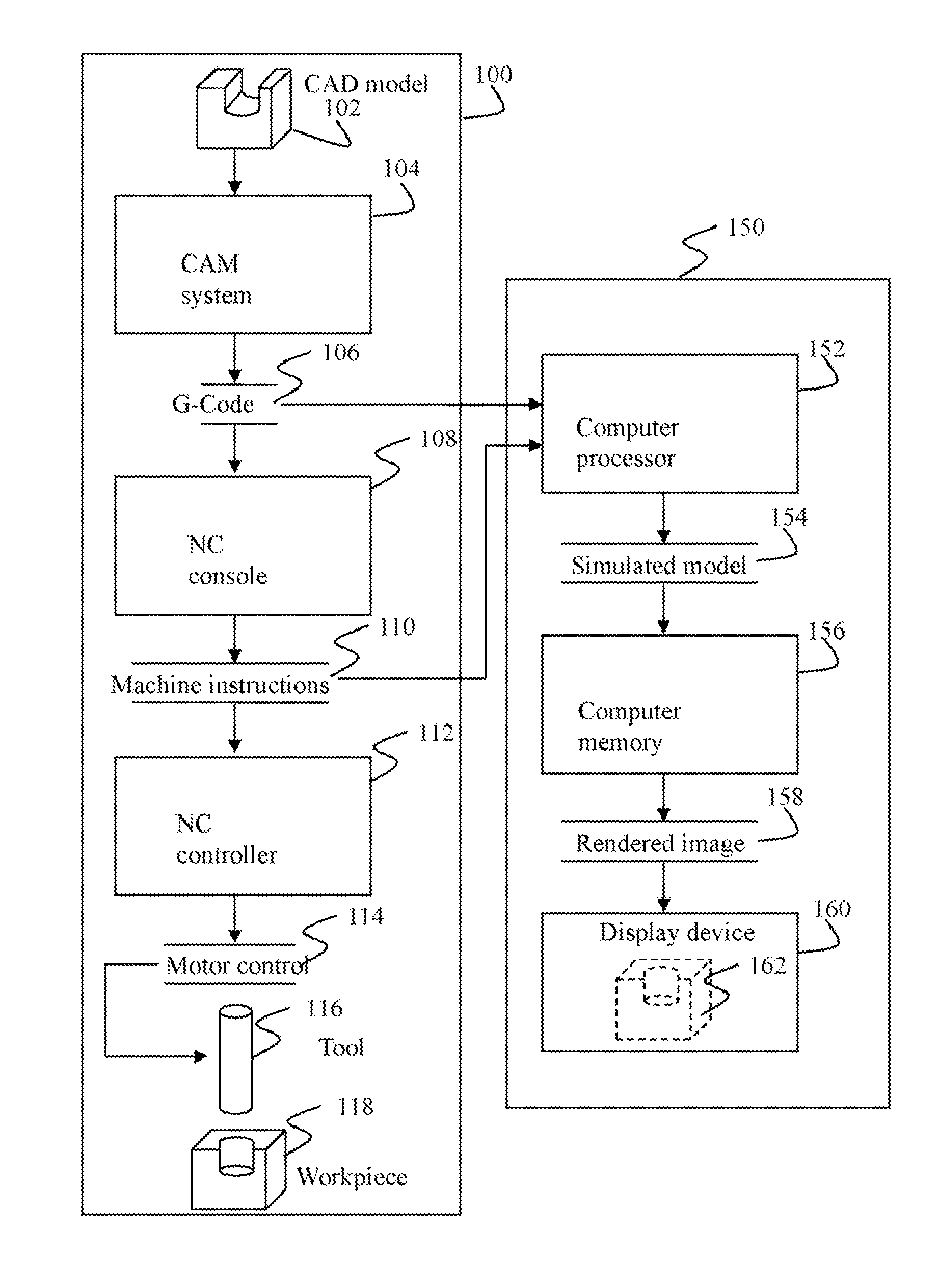
[0072]FIG. 1 shows an NC milling system 100, and a numerically controlled (NC) milling simulation system 150. In the NC milling system 100, a computer aided design (CAD) model 102 is input to a computer aided manufacturing (CAM) system 104, which generates G-Codes 106 for controlling an NC milling machine. During NC milling, the G-Codes are input to an NC milling input interface 108, which processes each G-Code to produce a corresponding set of NC machine instructions 110. The NC machine instructions are input into an NC controller 112, which produces a set of motor control signals 114 to move a tool 116 relative to a workpiece 118 in order to mill the workpiece.

[0073]The simulation system 150 can take as input either the G-Codes 106 generated by the computer aided manufacturing system 104, or the NC machine instructions 110 generated by the NC console 108. The input to the simulation system is read by a computer processor 152, which simulates machini...


PUM


Abstract

A method determines an engagement surface between a tool and a workpiece during a simulation of a machining of the workpiece by a relative motion between the object and the tool. A set of points is arranged on at least a part of a surface of the tool. A distance between each point in the set of points and a surface of the workpiece modified by the motion is determined and the engagement surface is formed based on a subset of points having the distance below a threshold.

Description

FIELD OF THE INVENTION[0001]The invention relates generally to analyzing engagement surface between an object and a shape intersecting the object, and more particularly to determining an angle of engagement or an area of engagement between a tool and a workpiece during a simulation of a machining of the workpiece by a motion of the tool.BACKGROUND OF THE INVENTIONNC Milling[0002]Simulating the process of numerically controlled (NC) milling is of fundamental importance in computer aided design (CAD) and computer aided manufacturing (CAM). During simulation, a computer model of a workpiece is edited with a computer representation of an NC milling tool and a set of NC milling tool motions to simulate the milling process.[0003]The workpiece model and tool representation can be visualized during the simulation to detect potential collisions between parts, such as the workpiece and the tool holder, and after the simulation to verify the final shape of the workpiece.[0004]The final shape o...

Claims


Application Information

Patent Timeline
Patent Type & Authority Applications(United States)
IPC IPC(8): G06G7/48
CPCG06F17/5086G06F17/5009G05B2219/45145G05B2219/35158G05B19/4069G06F30/17G06F30/20
Inventor ERDIM, HUSEYINSULLIVAN, ALAN
Owner MITSUBISHI ELECTRIC RES LAB INC
Why Eureka
Try Eureka