Turbocharger waste gate

a waste gate and turbocharger technology, applied in the direction of machines/engines, electric control, combustion engines, etc., can solve the problems that the turbocharger may not be able to respond to changes in engine load as fast, and achieve the effects of increasing engine output, increasing cylinder charge density, and improving engine outpu

Active Publication Date: 2013-10-10
FORD GLOBAL TECH LLC
View PDF11 Cites 7 Cited by
  • Summary
  • Abstract
  • Description
  • Claims
  • Application Information

AI Technical Summary

Benefits of technology

[0002]A turbocharger may be coupled to an engine to improve engine output. The turbocharger increases engine output via providing compressed air to the engine. More specifically, an amount of fuel provided to the engine is increased as the amount of air provided to the engine increases so as to increase cylinder charge density, thereby increasing engine torque. However, a turbocharger may not be able to respond to changes in engine load as fast as is desired because of turbine inertia and pumping delays through the engine. One way to improve turbocharger response is to reduce a size ...

Problems solved by technology

However, a turbocharger may not be able to respond to changes in engine load as...

Method used


Image

  • Turbocharger waste gate
  • Turbocharger waste gate
  • Turbocharger waste gate

Examples


Embodiment Construction

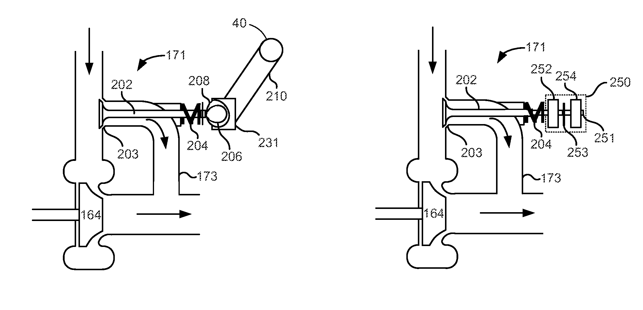
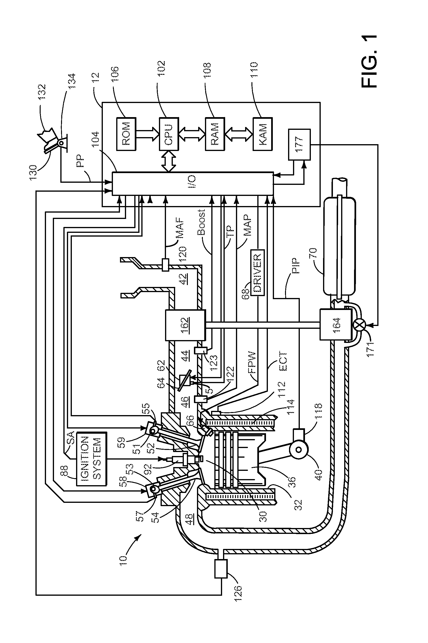
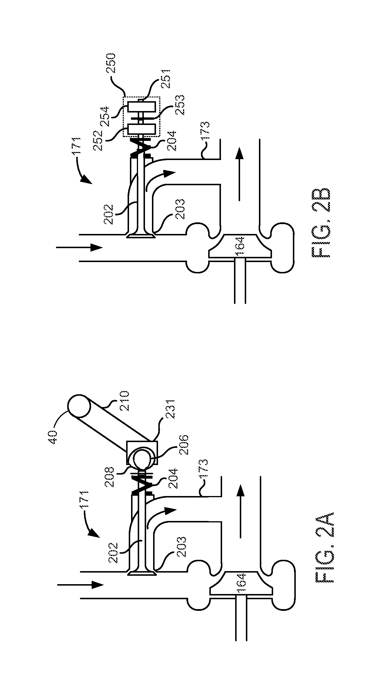
[0013]The present description is related to providing a waste gate that improves engine response and turbocharger efficiency. The description also includes a method for operating a turbocharger waste gate. In one example, the turbocharger and waste gate may be part of a system as shown in FIG. 1. The waste gate may be mechanically operated such as shown in the example of FIG. 2A. In other examples, the waste gate may be pneumatically, hydraulically, or electrically operated. FIG. 2B shows one example electromechanically operated waste gate. FIG. 3 is an example simulated plot that illustrates the benefits of operating the waste gate according to the method of FIG. 4.

[0014]In one example, the waste gate may operate synchronously with the engine. For example, the waste gate may open or close at specific times or crankshaft angles that coincide with specific engine events. In one example, the waste gate opens each time an exhaust valve of a cylinder opens delivering exhaust to the engi...


PUM


Abstract

A method for operating turbocharger waste gate is disclosed. In one example, the method operates the waste gate synchronous with engine operation. The approach may reduce turbocharger lag and improve turbocharger efficiency.

Description

FIELD [0001]The present description relates to operation of a turbocharger waste gate for an internal combustion engine. The waste gate may be operated to improve turbocharger efficiency and reduce lag time.BACKGROUND AND SUMMARY [0002]A turbocharger may be coupled to an engine to improve engine output. The turbocharger increases engine output via providing compressed air to the engine. More specifically, an amount of fuel provided to the engine is increased as the amount of air provided to the engine increases so as to increase cylinder charge density, thereby increasing engine torque. However, a turbocharger may not be able to respond to changes in engine load as fast as is desired because of turbine inertia and pumping delays through the engine. One way to improve turbocharger response is to reduce a size of a turbine exhaust inlet. By reducing the turbine inlet size, the velocity of exhaust gas entering the turbine increases and improves turbocharger response. On the other hand,...

Claims


Application Information

Patent Timeline
IPC IPC(8): F02D23/00
CPCF02D13/0265F02D23/02F02B2075/125F02B37/18F02B37/183F02D41/009F02D41/0007F02B2037/122Y02T10/144Y02T10/12
Inventor YAMADA, SHUYA S.MIAZGOWICZ, KEITH D.
Owner FORD GLOBAL TECH LLC
Why Eureka
Try Eureka