Plenoptic camera apparatus

Inactive Publication Date: 2013-10-10
SAMSUNG ELECTRONICS CO LTD
View PDF26 Cites 47 Cited by
  • Summary
  • Abstract
  • Description
  • Claims
  • Application Information

AI Technical Summary

Benefits of technology

[0015]Accordingly, embodiments of the present invention have been made to solve the above-stated problems occurring in the prior art. Specifically, a plenoptic camera apparatus is configured to switch

Problems solved by technology

The conventional plenoptic camera, however, has limitations.
Thus, the ov

Method used


Image

  • Plenoptic camera apparatus
  • Plenoptic camera apparatus
  • Plenoptic camera apparatus

Examples


Embodiment Construction

[0028]Hereinafter, embodiments of the present invention are described with reference to the accompanying drawings. Further, various specific definitions found in the following description are provided only to help general understanding of the present invention, and it will be understood by those skilled in the art that various changes and modifications can be made thereto within the technical spirit and scope of the present invention. In the following description, a detailed explanation of known related functions and constitutions may be omitted to avoid unnecessarily obscuring the subject matter of the present invention.

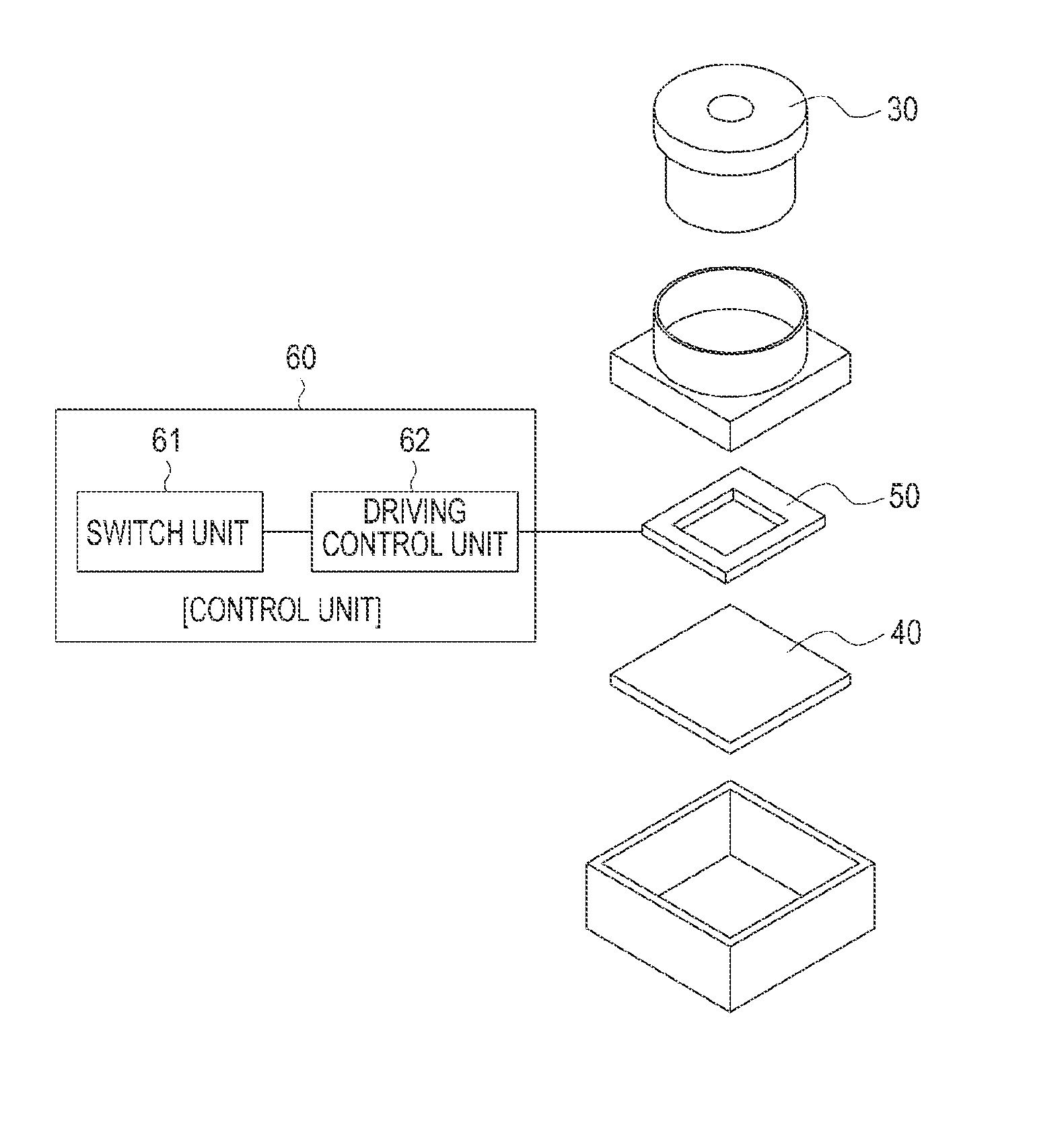
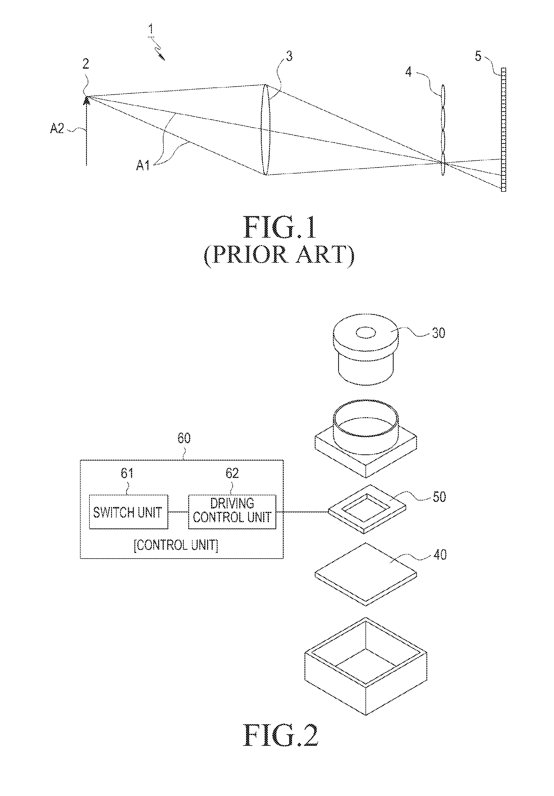
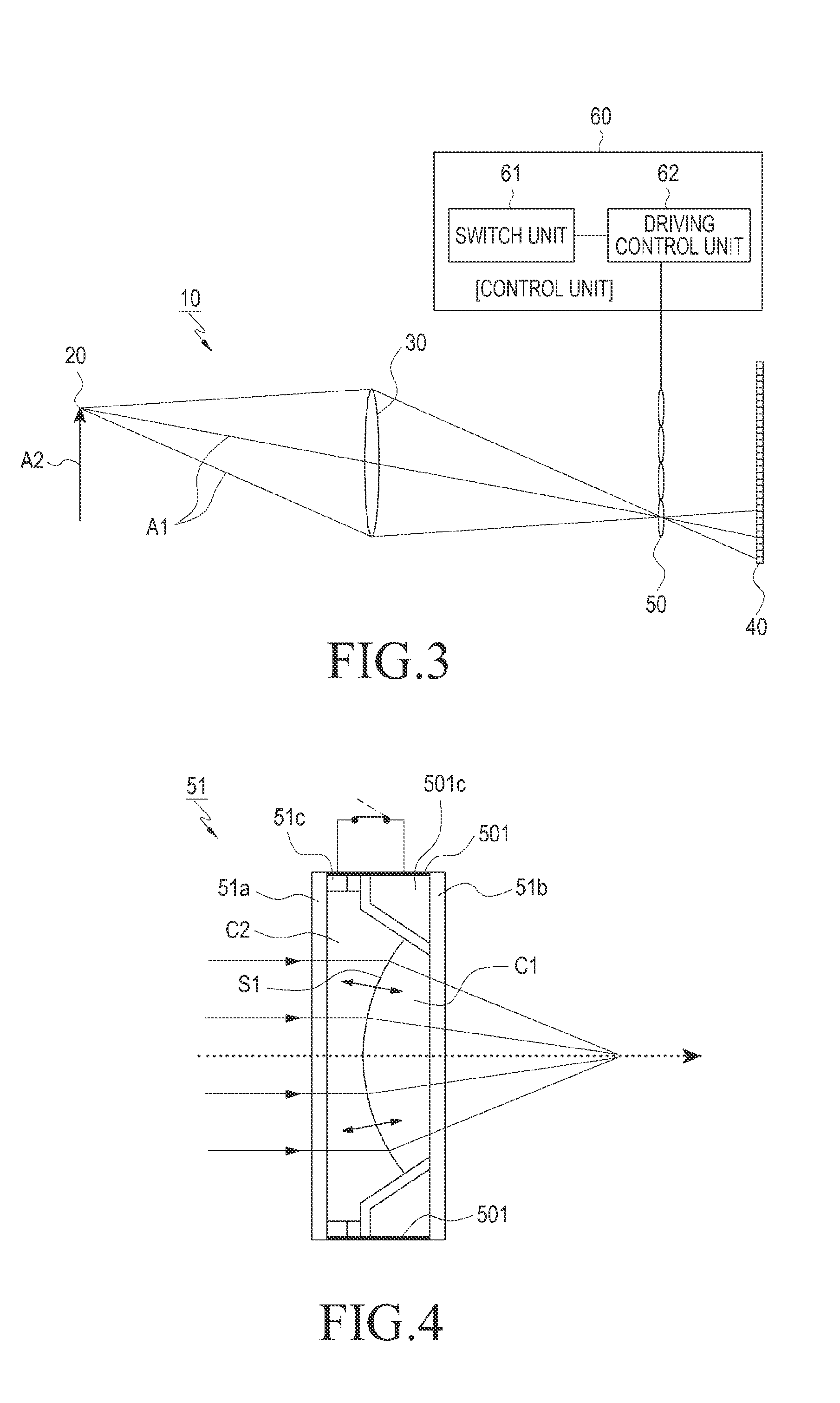
[0029]FIGS. 2 and 3 illustrate the construction of a plenoptic camera apparatus according to an embodiment of the present invention.

[0030]The plenoptic camera apparatus 10 includes a main lens unit 30, an image sensor unit 40, one or more convertible lens device units 50, and a control unit 60. The main lens unit 30 is configured to collect rays Al emitted from a su...


PUM


Abstract

A plenoptic camera apparatus includes a main lens unit configured to collect rays emitted from a subject. The plenoptic camera apparatus includes an image sensor unit adapted to capture images formed from the collected rays through one or more convertible lens device units. The convertible lens device units are positioned between the main lens unit and the image sensor unit and configured to provide individual curvature adjustment. The plenoptic camera apparatus includes a control unit configured to control the convertible lens device units to switch to a high-resolution imaging lens or a plenoptic imaging lens array, based on a user's selection, and control driving of the convertible lens device units to compensate for a partial aberration caused by the main lens unit.

Description

PRIORITY[0001]This application claims priority under 35 U.S.C. §119(a) to a Korean Patent Application filed in the Korean Industrial Property Office on Apr. 4, 2012 and assigned Ser. No. 10-2012-0035004, the contents of which are incorporated herein by reference.BACKGROUND OF THE INVENTION[0002]1. Field of the Invention[0003]The present invention relates generally to a plenoptic camera apparatus, and more particularly, to a plenoptic camera apparatus providing high-resolution imaging and plenoptic imaging.[0004]2. Description of the Related Art[0005]Conventional commercialized imaging systems provide only one image from a single imaging operation. A plenoptic camera has recently been developed, which has a function of recombining foci.[0006]The plenoptic camera, also referred to as a light field camera, employs a microlens array or a light-coded mask to capture 4D light field information.[0007]The plenoptic camera allows the user to change the focus plane after an imaging operation....

Claims


Application Information

Patent Timeline
IPC IPC(8): H04N5/225
CPCH04N5/225G02B27/0025H04N5/23245H04N5/2254H04N23/957H04N23/667G03B35/00G03B41/00H04N23/00
Inventor KANG, BYUNG-KWON
Owner SAMSUNG ELECTRONICS CO LTD
Why Eureka
Try Eureka