Optical gas sensor

Active Publication Date: 2013-10-10
DRAGER SAFETY
View PDF3 Cites 14 Cited by
  • Summary
  • Abstract
  • Description
  • Claims
  • Application Information

AI Technical Summary

Benefits of technology

[0006]An object of the present invention is to provide an optical gas sensor, which permi

Problems solved by technology

However, this causes a lot of energy to flow into spectral ranges that are not used to analyze and calculate gas concentrations.
Such gas sensors therefore have low efficiency in terms of their energy consumption.
In addition, their output cannot be modified rapidly without additional mechanical components, which limits the use of noise suppression method

Method used


Image

  • Optical gas sensor
  • Optical gas sensor
  • Optical gas sensor

Examples


Embodiment Construction

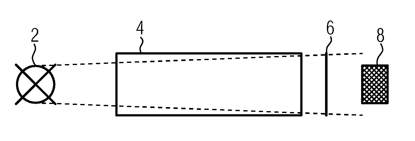
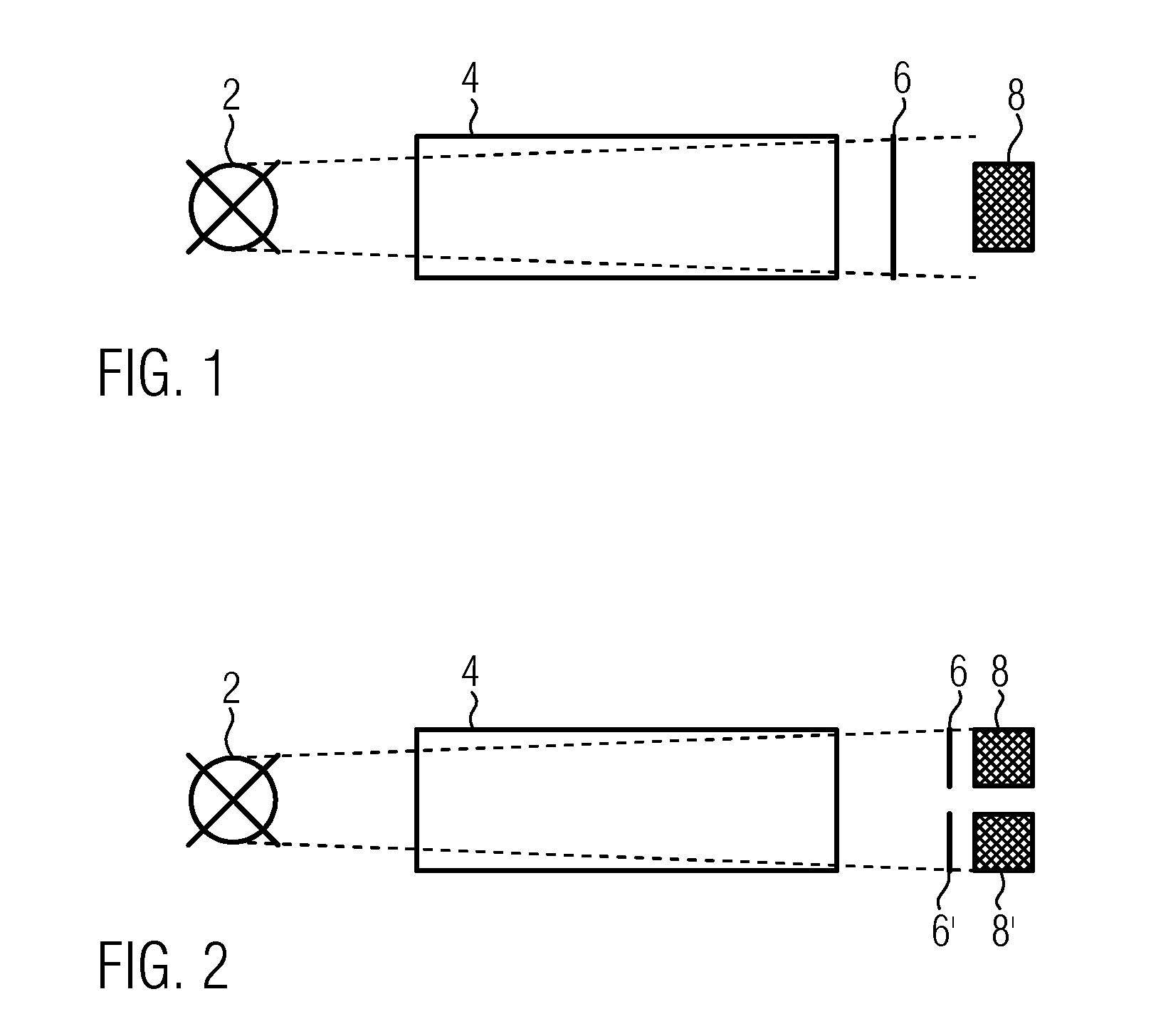
[0025]Referring to the drawings in particular, FIG. 1 schematically shows the design of an optical gas sensor. The gas sensor has a light-emitting diode 2 and a photosensor 8 in the form of a photodiode. A measuring section is located between sensor 2 and photodiode 8, a gas sample holder 4 containing the gas to be measured being shown in this example. A narrow frequency band, in which the target gas to be measured possesses characteristic spectral properties, is cut out of the wavelength spectrum, which passes through the measuring section starting from the light-emitting diode 2, by means of a band pass filter 4. The target gas may have, for example, a known high absorbing capacity in the spectral range of interest. The concentration of the target gas can thus be calculated from the determination of the absorption.

[0026]FIG. 2 shows a gas sensor having a similar design, which does, however, have another photodiode 8′ behind another band pass filter 6′ besides a photodiode 8 behind...


PUM


Abstract

An optical gas sensor with a light-emitting diode (2), a photosensor (8), a measuring section between the light-emitting diode and the photosensor, and a control and analyzing unit (16), which is set up to determine the concentration of a gas in the measuring section from the light intensity measurement by the photosensor. The control and analyzing unit (16) is set up to measure the forward diode voltage over the light-emitting diode at a constant current, to determine the temperature of the light-emitting diode from the detected forward diode voltage over the light-emitting diode by means of a preset temperature dependence of the forward diode voltage, and to apply a correction function as a function of the light-emitting diode temperature determined, with which the measurement is converted to that of a preset temperature of the light-emitting diode.

Description

CROSS REFERENCE TO RELATED APPLICATIONS[0001]This application claims the benefit of priority under 35 U.S.C. §119 of German Patent Application DE 10 2012 007 016.0 filed Apr. 5, 2012, the entire contents of which are incorporated herein by reference.FIELD OF THE INVENTION[0002]The present invention pertains to an optical gas sensor with a light-emitting diode, a photosensor, a measuring section between light-emitting diode and photosensor, and a control and analyzing unit, which is set up to determine the concentration of a gas in the measuring section on the basis of the measurement performed by the photosensor.BACKGROUND OF THE INVENTION[0003]Optical gas sensors operate with a light source (radiation source), a photosensor and a measuring section located between the light source and the photosensor. A wavelength range, in which the target gas has a characteristic absorption, can be selected with a band pass filter. Thermal light sources, such as diaphragm sources or spiral-wound f...

Claims


Application Information

Patent Timeline
IPC IPC(8): G01N21/17
CPCG01N21/3504G01N21/17G01N21/274G01N33/0004
Inventor BECKMANN, UDOFORNASIERO, LIVIO
Owner DRAGER SAFETY
Why Eureka
Try Eureka