Coaxial connector with ingress reduction shield

Inactive Publication Date: 2013-10-10
HOLLAND ELECTRONICS
View PDF3 Cites 18 Cited by
  • Summary
  • Abstract
  • Description
  • Claims
  • Application Information

AI Technical Summary

Benefits of technology

[0020]The present invention provides a shield against unwanted radio frequency (“RF”) transfer in coaxial cable installations. Shielding devices of

Problems solved by technology

These prior art connectors may become the source of future problems as proliferation of RF devices such as cellular telephones increases the chances RF ingress will adversely affect interconnected systems such as cable television and satellite television signal distribution systems.
And, past efforts have limited some sources of the ingress of interfering RF signals into CATV systems.
A significant location of unwanted RF signal and noise ingress into CATV systems is in the home.
An open connector end exposes a normally metallically enclosed and shielded signal conductor and can be a major source of unwanted RF ingress.
As will be appreciated, multiple CATV connections in a home increase the likelihood that some connections will be left unused and open, making them a source of unwanted RF ingress.
And, when subscribers move

Method used


Image

  • Coaxial connector with ingress reduction shield
  • Coaxial connector with ingress reduction shield
  • Coaxial connector with ingress reduction shield

Examples


Example

[0047]The disclosure provided herein describes examples of some embodiments of the invention. The designs, figures, and descriptions are non-limiting examples of the embodiments they disclose. For example, other embodiments of the disclosed device and / or method may or may not include the features described herein. Moreover, disclosed advantages and benefits may apply to only certain embodiments of the invention and should not be used to limit the disclosed invention.

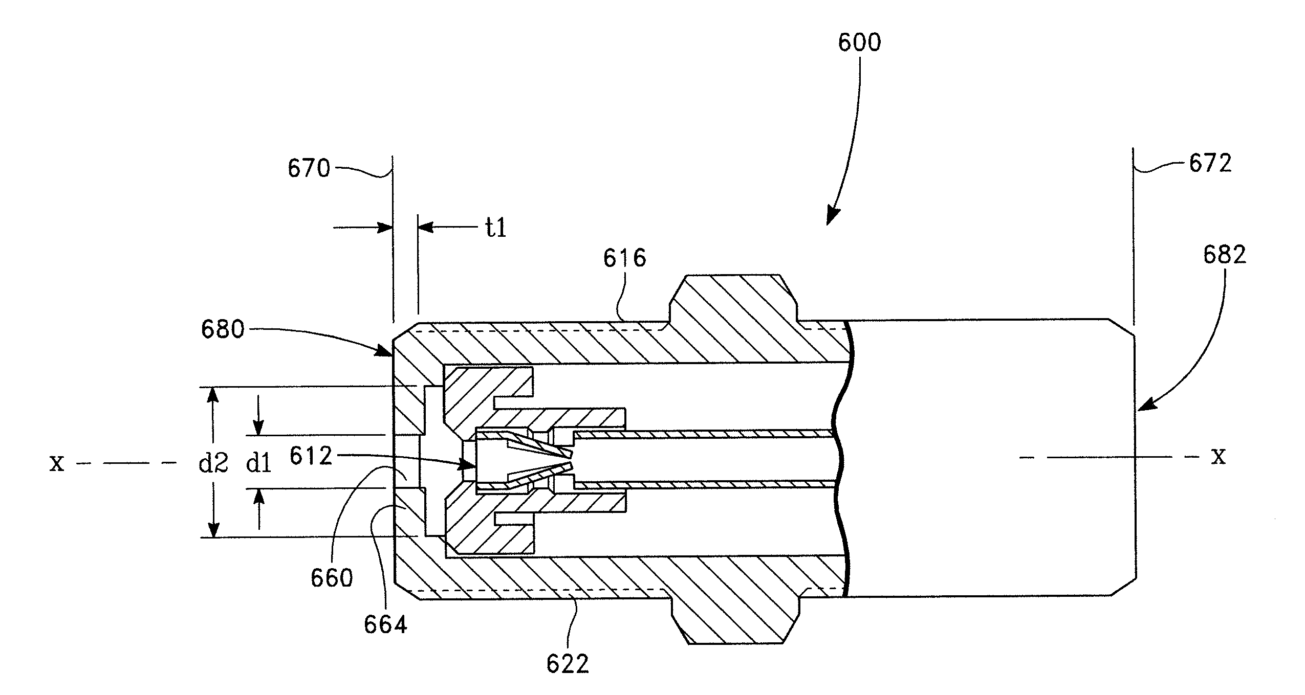
[0048]Embodiments of the invention provide a method of reducing RF cable interconnection ingress. In various embodiments, cable interconnection RF ingress is reduced by including a filter such as a waveguide and / or a screen at the cable entry end of an F-Type female port. Examples include filters that are frequency and / or frequency range specific.

[0049]Restriction of the ingress of RF frequencies may be for particular applications such as restricting frequencies below 100 MHz for CATV applications and specific frequencie...


PUM


Abstract

A coaxial connector with an F female end shield is configured to restrict RF ingress.

Description

PRIORITY CLAIM[0001]The present invention claims the benefit of U.S. Provisional Patent Application 61 / 620,355 filed Apr. 4, 2012 and entitled COAXIAL CONNECTOR WITH INGRESS REDUCTION SHIELD.BACKGROUND OF THE INVENTION[0002]1. Field of the Invention[0003]The present invention relates to an article of manufacture for conducting electrical signals. In particular, F-Type connectors are equipped to reject RF ingress.[0004]2. Discussion of the Related Art[0005]FIGS. 1, 2, 3A-C, and 4 show prior art F-Type connectors. FIG. 1 shows a perspective view 100 of a prior art F female port 102 mounted to a wall disk 104. FIG. 2 shows a side view 200 of FIG. 1 revealing a coaxial cable 208 attached via a F male connector 206 to the F female port and leaving a room facing attachment end 204 of the F female port exposed to stray signals or RF ingress 210.[0006]FIGS. 3A-C show a cross-sectional view 300A, side view 300B and a perspective view 300C of a prior art F splice with female ports 332, 334 at...

Claims


Application Information

Patent Timeline
IPC IPC(8): G02B6/38
CPCH01R24/44G02B6/3869
Inventor HOLLAND, MICHAEL
Owner HOLLAND ELECTRONICS
Why Eureka
Try Eureka