Maintenance tool for insulator of direct current transmission line
a technology of insulator and transmission line, which is applied in the field of maintenance tools for insulators on direct current transmission lines, can solve the problems of far from the replacement requirements of maintenance tools, and achieve the effects of low volume, light weight and high overall strength
- Summary
- Abstract
- Description
- Claims
- Application Information
AI Technical Summary
Benefits of technology
Problems solved by technology
Method used
Image
Examples
first embodiment
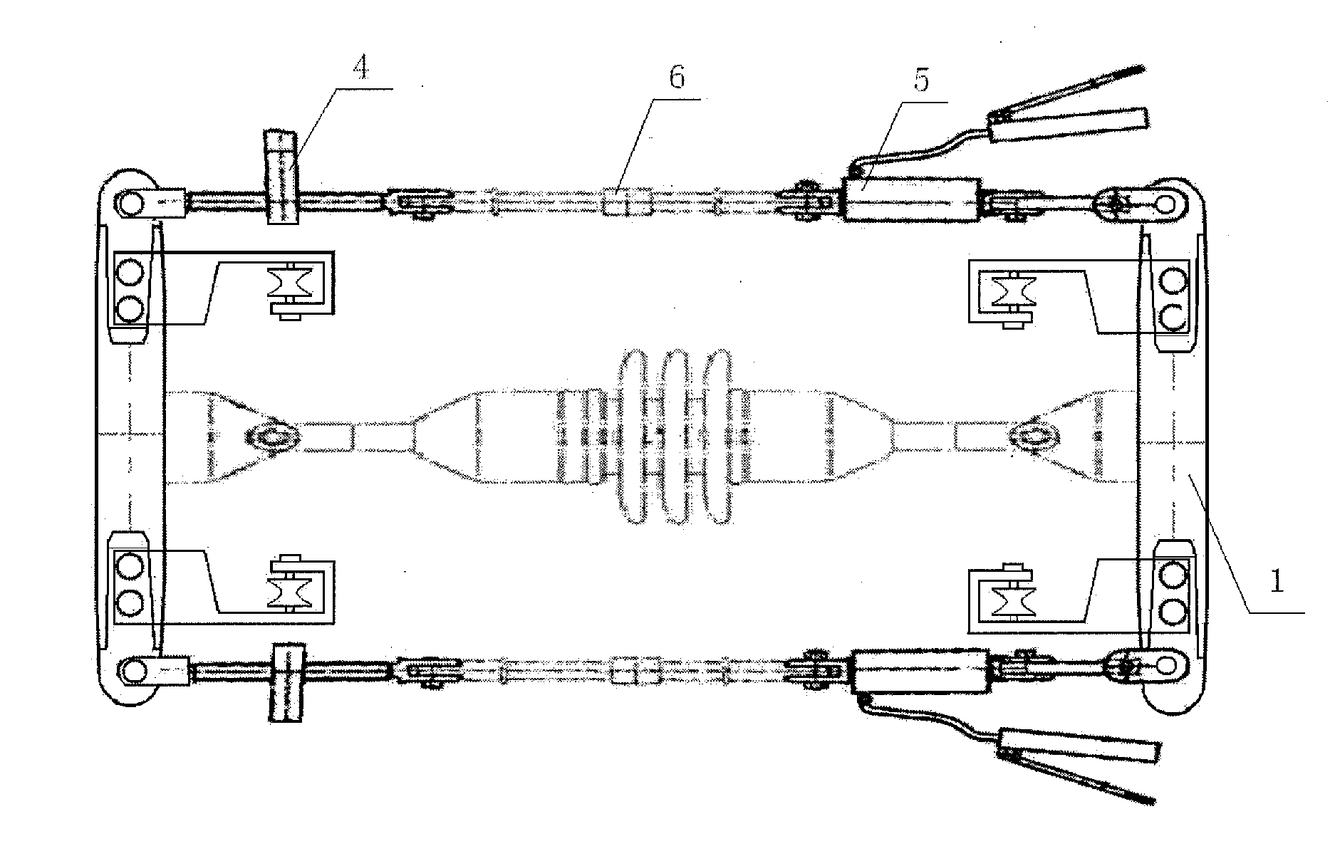
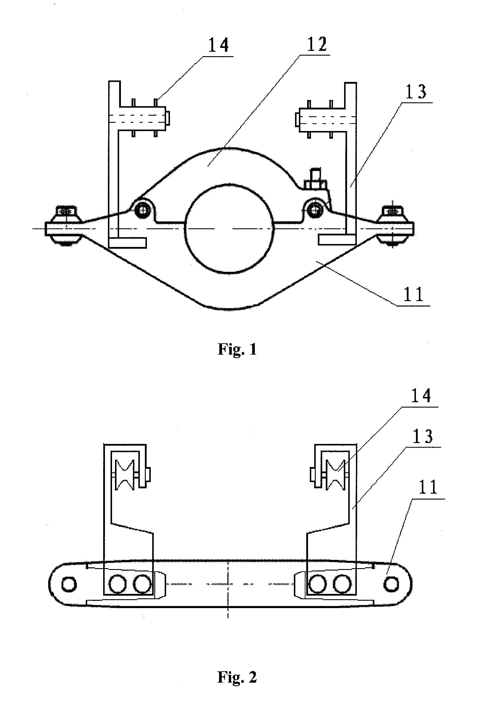
[0031]In a case that the present application is use for replacing a single insulator, multiple insulators in the middle portion or a long rod insulator on a 660 kV direct current transmission line, two closed clamps and two tension devices are sufficient, as shown in FIG. 6. The upper cover of the closed clamp is opened, and is rotated to one side of the closed clamp main body about a pin shaft. Then the closed clamp is clamped on a steel cover at one of two ends of the insulator, and then the upper cover is covered to its original position. Then the upper cover and the closed clamp main body is fixedly connected via a bolt, thereby the closed clamp is fixedly connected on the insulator. Then the mechanical transmission screw rods and the hydraulic devices of the two tension devices are respectively connected to pin holes at ends of the two closed clamps, and then the insulation pulling rod 6 is connected between the mechanical transmission screw rod and the hydraulic device, so as ...
second embodiment
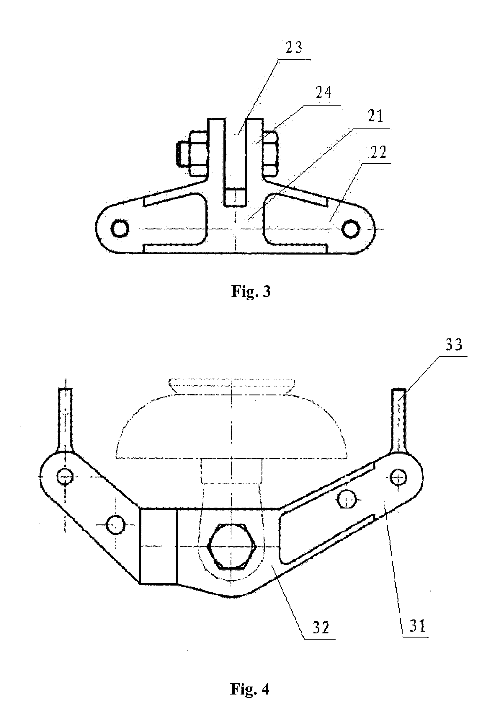
[0033]When replacing a first insulator at a wire end on a 660 kV direct current transmission line, a composition of the wire end clamp, the closed clamp and the tension device is used, as shown in FIG. 7. The difference between the second embodiment and the first embodiment lie in that: one closed clamp is clamped on the steel cover of the first insulator at the wire end; then the plate turning clamp of the wire end clamp is rotated to one side of the wire end clamp main body about a pin shaft such that the wire end yoke plate is clamped between the wire end clamp main body and the plate turning clamp, then the nut on the wire end yoke plate is inserted into the bolt hole of the wire end clamp; and then the other end of the plate turning clamp is fixedly connected with the wire end clamp main body via a bolt; next the mechanical transmission screw rod and the hydraulic device of the tension device is connected between the closed clamp and the wire end clamp, and the insulation pulli...
third embodiment
[0035]When replacing a first insulator at a crossarm end on a 660 kV direct current transmission line, a composition of the single string clamp, the closed clamp and the tension device is used, as shown in FIG. 8. The difference between the third embodiment and the second embodiment lie in that, one closed clamp is mounted on the steel cover of the first insulator at the crossarm end; then the insert plate, having the clamping groove, of the single string clamp is mounted on the towing plate such that the connecting hole on the towing plate is aligned with the pin hole of the single string clamp, then a bolt is passed through the holes such that the single string clamp is fixedly connected with the towing plate.
PUM
| Property | Measurement | Unit |
|---|---|---|
| length | aaaaa | aaaaa |
| length | aaaaa | aaaaa |
| distance | aaaaa | aaaaa |
Abstract
Description
Claims
Application Information
 - R&D
- Intellectual Property
- Life Sciences
- Materials
- Tech Scout
- Unparalleled Data Quality
- Higher Quality Content
- 60% Fewer Hallucinations
Browse by: Latest US Patents, China's latest patents, Technical Efficacy Thesaurus, Application Domain, Technology Topic, Popular Technical Reports.
© 2025 PatSnap. All rights reserved.Legal|Privacy policy|Modern Slavery Act Transparency Statement|Sitemap|About US| Contact US: help@patsnap.com


