
Large-area transmissive type optical image modulator and method of manufacturing the same and optical apparatus including transmissive type optical image modulator

Active Publication Date: 2013-10-17
SAMSUNG ELECTRONICS CO LTD
View PDF8 Cites 22 Cited by
  • Summary
  • Abstract
  • Description
  • Claims
  • Application Information

AI Technical Summary

Benefits of technology

The patent text describes an optical image modulator that can drive at high speeds and has uniform response across a large area. It is also more tolerant to mechanical changes and impact than other similar devices.

Problems solved by technology

However, when these methods are used, as the distance between the camera and the object is increased, precision may rapidly decrease.
Also, these methods are dependent on a surface state of an object, and thus it may be difficult to obtain a minute range image.
In order to perform modulation and demodulation inside a CCD cell, an additional function of processing signals around the CCD is required, and thus a fill factor deteriorates and a size of the CCD cell is increased, thereby imposing limitations in forming a high resolution distance camera.
Such an optical modulator is bulky, uses a high voltage of several KV, and is expensive.
However, a series of processes, in which a substrate of an expitaxial structure in which an electrode is formed during a process of manufacturing a wafer level is removed and transferred to another substrate, that is, an SiO2 substrate, may be complex, and thus it may be difficult to stably perform the processes.
Recently, although a transmissive optical modulator, in which a portion through which light passes is removed from a conventional opaque substrate and a transparent InGaP layer is added to an expitaxial layer to be used as a support for supporting an expitaxial structure, has been introduced, an expitaxial thin film may be vulnerable to an external impact or a mechanical transformation.

Method used


Image

  • Large-area transmissive type optical image modulator and method of manufacturing the same and optical apparatus including transmissive type optical image modulator
  • Large-area transmissive type optical image modulator and method of manufacturing the same and optical apparatus including transmissive type optical image modulator
  • Large-area transmissive type optical image modulator and method of manufacturing the same and optical apparatus including transmissive type optical image modulator

Examples


Embodiment Construction

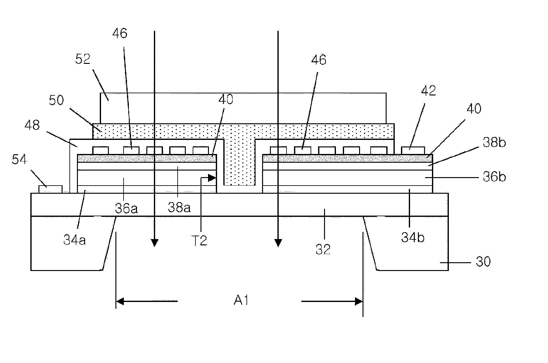
[0068]Hereinafter, exemplary embodiments will he described in detail with reference to the attached drawings. In the drawings, the thicknesses of layers and regions may be exaggerated for clarity. Expressions such as “at least one of,” when preceding a list of elements, modify the entire list of elements and do not modify the individual elements of the list.

[0069]First, a transmissive type optical image modulator according to an exemplary embodiment will be described.

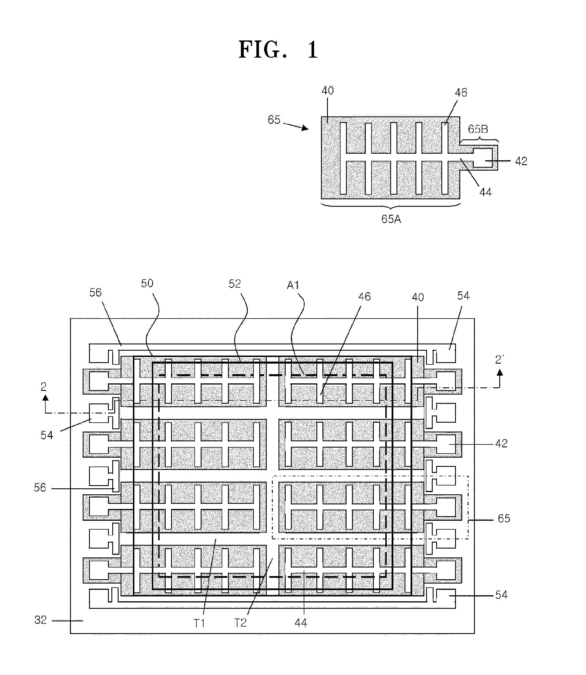
[0070]FIG. 1 is a plan view of an optical image modulator according to an exemplary embodiment.

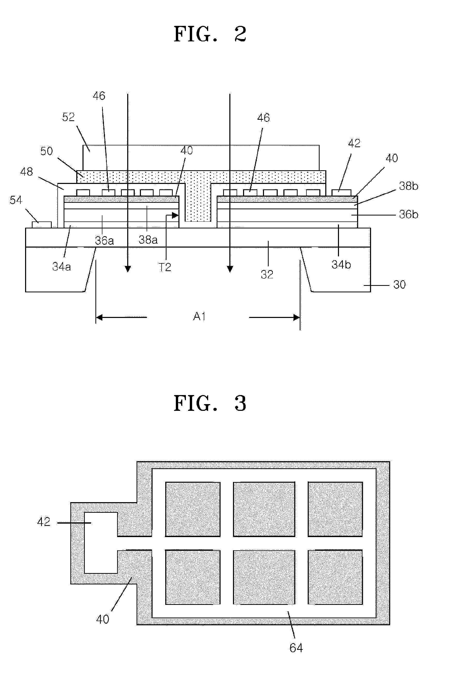
[0071]Referring to FIG. 1, the large-area optical image modulator includes a plurality of unit optical modulators 65 forming an array. The unit optical modulators 65 may be unit modulation areas. The unit optical modulators 65 are disposed to be vertically and bilaterally symmetrical to one another. The unit optical modulators 65 are spaced apart from one another. First and second trenches T1 and T2 are formed between the unit...


PUM


Abstract

A large-area transmissive type optical image modulator, a method of manufacturing the same, and an optical apparatus including the transmissive type optical image modulator are provided. The large-area transmissive type optical image modulator includes: a base substrate; a first expitaxial layer formed on the base substrate; a second expitaxial layer formed on the first expitaxial layer; a first electrode formed on the first expitaxial layer and spaced apart from the second expitaxial layer; a second electrode formed on the second expitaxial layer; and a transparent substrate covering the second expitaxial layer and the second electrode, wherein the base substrate includes a through hole corresponding to a light emitting area, and the first expitaxial layer may include an n-type or p-type doping material.

Description

CROSS-REFERENCE TO RELATED APPLICATION[0001]This application claims priority from Korean Patent Application No. 10-2012-0038171, filed on Apr. 12, 2012, in the Korean Intellectual Property Office, the disclosure of which is incorporated herein in its entirety by reference.BACKGROUND[0002]1. Field[0003]Apparatuses and methods consistent with exemplary embodiments relate to an optical device, and more particularly, to a large-area transmissive type optical image modulator and a method of manufacturing the same, and an optical apparatus including the transmissive type optical image modulator.[0004]2. Description of the Related Art[0005]In order to obtain information regarding a range image, a stereo vision method using two cameras and a triangulation method using structured light and a camera are used.[0006]However, when these methods are used, as the distance between the camera and the object is increased, precision may rapidly decrease. Also, these methods are dependent on a surface ...

Claims


Application Information

Patent Timeline
IPC IPC(8): G02F1/00G01C3/08H01L31/18
CPCG02F1/00H01L31/18G01C3/08G02F1/015G02F2203/12G02F1/0157H01L27/14H04N25/00
Inventor CHO, YONG-CHULLEE, SANG-HUNPARK, YONG-HWAPARK, CHANG-YOUNGKWON, JONG-OHYOU, JANG-WOOYOON, HEE-SUN
Owner SAMSUNG ELECTRONICS CO LTD
Learn More