
Well-logging tool for determining properties in a flowstream

a flowstream and well-logging technology, applied in the field of well-logging tools for determining properties in flowstreams, can solve the problems of limited success of tools, unable to make measurements responsive to full-scale measurement, and hampered the production of logging tools based on electrical resistivity

Active Publication Date: 2013-10-17
PROBE TECH
View PDF2 Cites 11 Cited by
  • Summary
  • Abstract
  • Description
  • Claims
  • Application Information

AI Technical Summary

Benefits of technology

The patent describes a method for measuring gas holdup, water salinity, and the degree of stream strification. This is done by using a long and short spaced detector to measure data in multiple energy ranges. The data is combined to determine these measurements, which are then iterated to improve accuracy and precision. The technical effect of this method is to provide accurate and precise information on gas and water contents of a flow stream.

Problems solved by technology

Many current generation production logging tools have had limited success in determining gas holdup since gas production often results in laminated, or partially laminated flowstreams, while the production logging tools, such as gamma-gamma fluid density logging tools, do not make measurements responsive to the full-bore flowstream.
Electrical resistivity based production logging tools have also been hampered by the fact that the electrical resistivities of oil and gas are both very high (and hard to distinguish), and the resistivity measurements are strongly dependent on the salinity of the water in the flowstream.
This measurement technique has been useful, but is limited by the fact that the single measurement made by the tool is sensitive to the flowstream lamination and salinity, in addition to gas holdup.
Unfortunately, a single count rate measurement cannot be used to resolve three unknown parameters.
The combination measurement disclosed in U.S. Pat. No. 5,552,598 is, however, still sensitive to water salinity effects and to situations when the gas and liquids are partially mixed.
The system disclosed in U.S. Pat. No. 5,552,598 also requires the use of two separate gamma ray sources thereby creating associated handling, storage, and safety issues.
The separate fluid density tool string and source also require additional capital and operational expenses.

Method used


Image

  • Well-logging tool for determining properties in a flowstream
  • Well-logging tool for determining properties in a flowstream
  • Well-logging tool for determining properties in a flowstream

Examples


Embodiment Construction

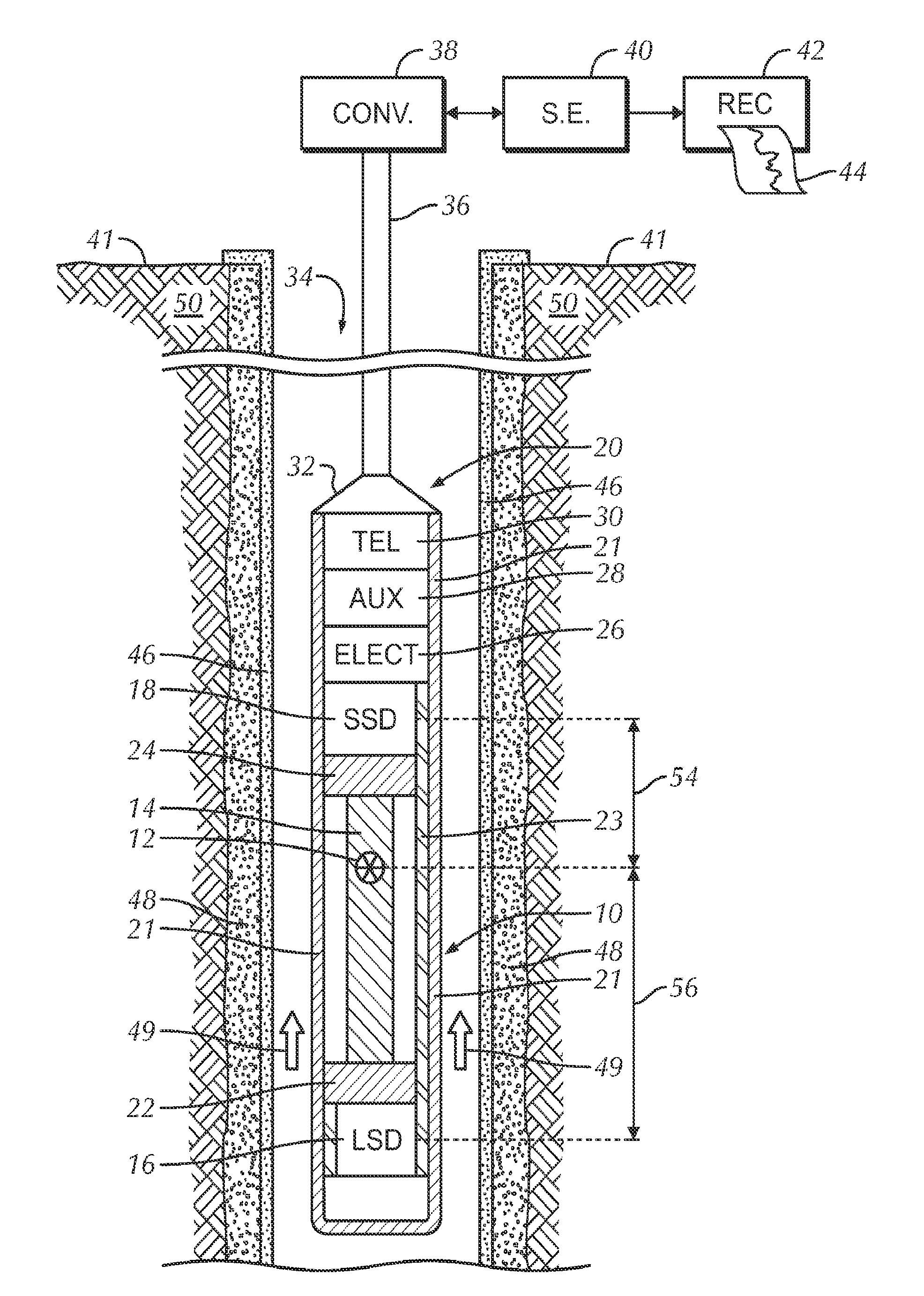
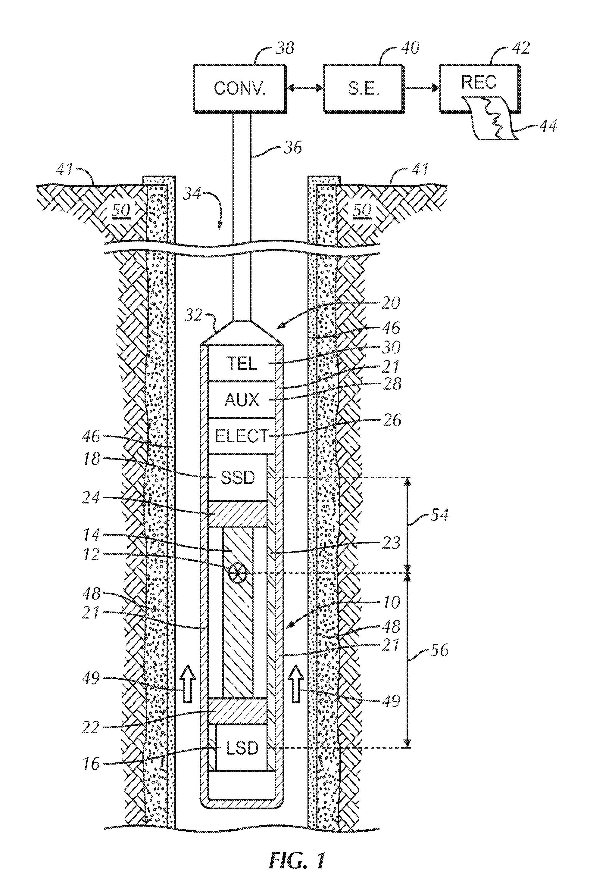
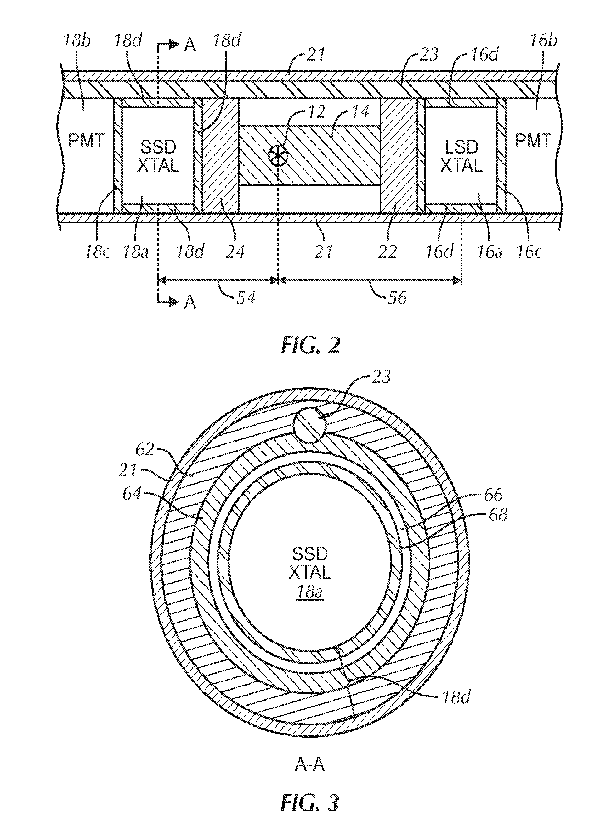
[0021]The detailed description of the SGHT will be described in detail in the following section. The system hardware is first presented. Basic tool response will next be disclosed. Responses were simulated using the Monte Carlo MCNP-X code. Finally, data processing methodology will be presented using specific production logging examples.

[0022]The SGHT is disclosed as a wireline logging system. The system can also be used as a tubing conveyed logging tool or a pump-down tool with spectral data being recorded in the tool for subsequent analysis at the surface of the earth. The tool can also be embodied conceptually as a logging-while-drilling (LWD) or measurement-while-drilling (MWD) providing that low Z material inserts can be disposed in the region of the source and gamma ray detectors. In this embodiment, measurements would typically be made when “tripping” the drill string rather than when advancing the borehole.

[0023]System Hardware

[0024]FIG. 1 illustrates the major elements of t...


PUM


Abstract

A full bore spectral gas holdup tool that measures gas holdup that is corrected for effects of the flowstream lamination and the salinity of the liquid in the a flowstream. The basic methodology utilizes spectral data from two gamma ray detectors at different spacings from a nuclear source that emits gamma radiation. 57Co is the preferred source and the gamma ray detectors are scintillation spectrometers. In addition to a full bore gas holdup measurement, the spectral gas holdup tool also provides indications of the degree of flowstream lamination and the salinity of the liquid in the flowstream. An iterative data processing method optimizes the accuracy of the measured flowstream parameters.

Description

CROSS REFERENCE TO RELATED APPLICATIONS[0001]This application is a U.S. National Phase Application of PCT / US2011 / 037694, filed May 24, 2011, which claims priority based on U.S. Provisional Application Serial No. 61 / 375,058 filed Aug. 19, 2010, both of which are hereby incorporated by reference in their entireties.FIELD OF THE INVENTION[0002]This invention is related to measurement of properties of a fluid flowstream, and more particularly related to a logging system that measures gas holdup, liquid component salinity, and the degree of fluid lamination in a borehole flowstream. Measurements are representative of flow within the entire flow conduit.BACKGROUND[0003]The determination and measurement of the different phases present in a multi-phase produced fluid flowstream in a cased wellbore is very useful information for oilfield operators in order for them optimize production from downhole reservoirs. Produced flowstreams typically comprise free gas, water, or oil in any combination...

Claims


Application Information

Patent Timeline
Patent Type & Authority Applications(United States)
IPC IPC(8): G01V5/12
CPCG01V5/12
Inventor MINETTE, DANIEL CARLSMITH, HARRY D.PHELPS, PHILLIP R.
Owner PROBE TECH
Learn More