
Quick charging system, control device, method of controlling amount of the stored electrical power, and program

a technology of electrical power storage and charging system, which is applied in the direction of electrochemical generators, secondary cells servicing/maintenance, transportation and packaging, etc., can solve the problems of storage battery not being able to charge with electrical power generated using renewable energy, and the amount of electrical power supplied per unit time from the power distribution network becoming too larg

Active Publication Date: 2013-10-17
NEC CORP
View PDF2 Cites 2 Cited by
  • Summary
  • Abstract
  • Description
  • Claims
  • Application Information

AI Technical Summary

Benefits of technology

This patent describes a system, device, method, and program for quickly charging and controlling the amount of electrical power stored using renewable energy. The system aims to maximize the amount of stored power and prevent it from becoming insufficient when supplying power to a battery. Overall, the patent provides a solution for efficiently managing and utilizing renewable energy.

Problems solved by technology

When charging a battery provided in an apparatus, such as an electrical vehicle, with electrical power, if the battery is charged directly from the power distribution network built by the power company or the power generator that generates electrical power using renewable energy, the amount of electrical power per unit time supplied from the power distribution network becomes too large.
However, if the supply of electrical power from the power distribution network is controlled such that the amount of the stored electrical power of the storage battery is always 100%, a timing, at which the storage battery cannot be charged with electrical power generated using renewable energy, may occur.

Method used


Image

  • Quick charging system, control device, method of controlling amount of the stored electrical power, and program
  • Quick charging system, control device, method of controlling amount of the stored electrical power, and program
  • Quick charging system, control device, method of controlling amount of the stored electrical power, and program

Examples


first embodiment

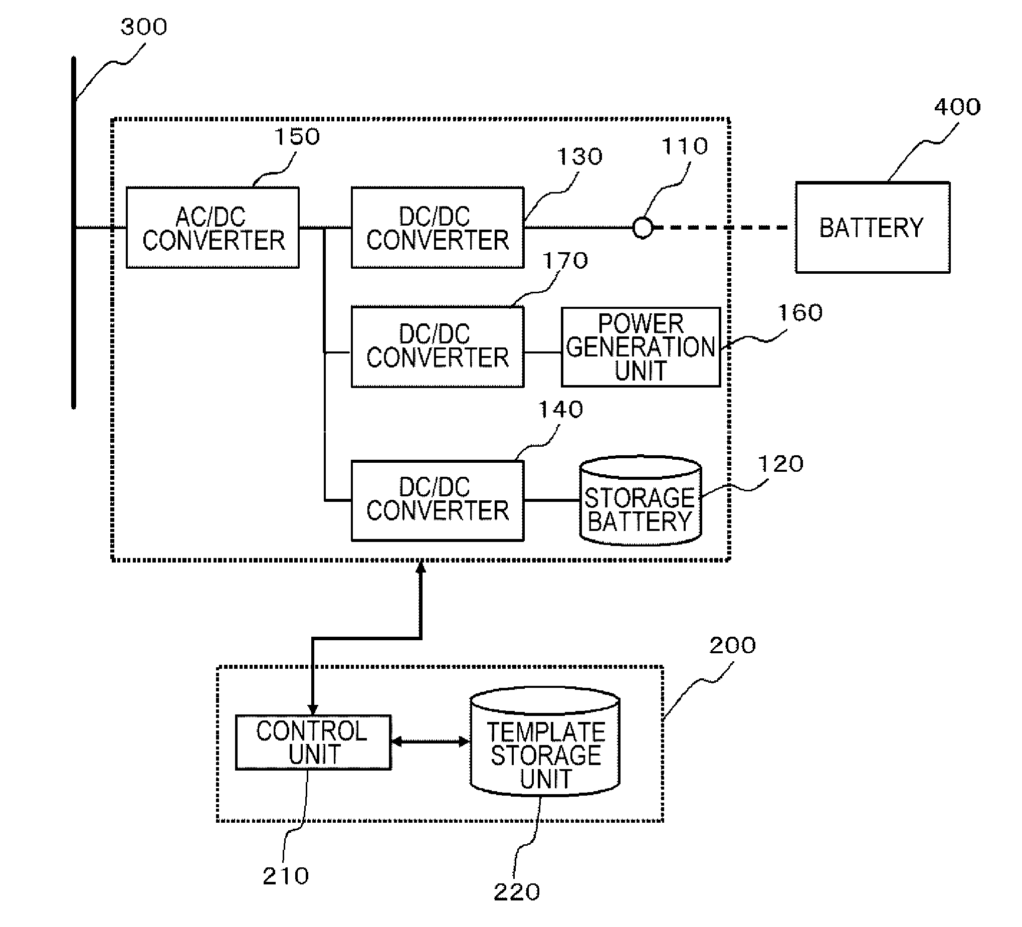
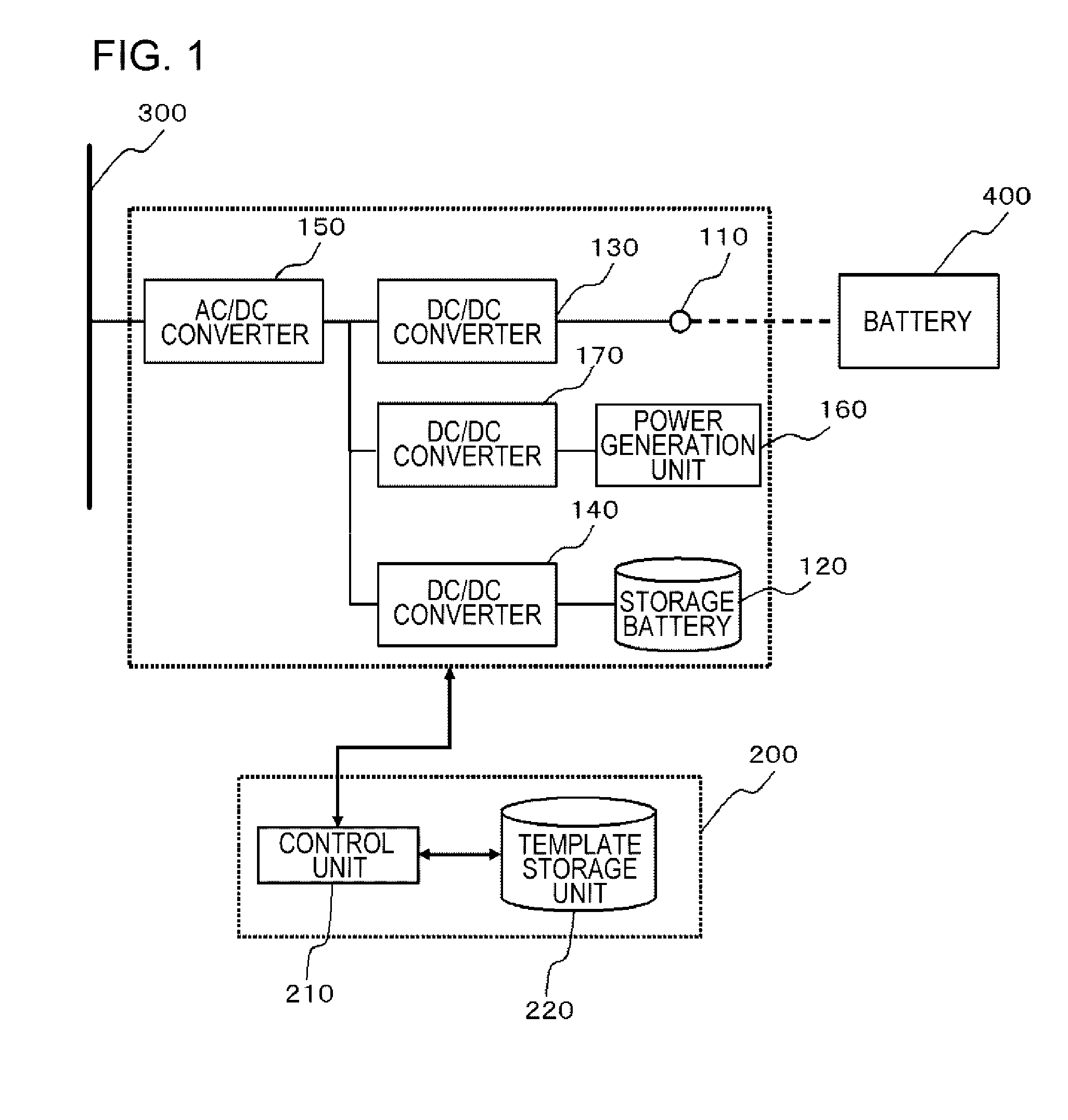
[0031]FIG. 1 is a block diagram showing the configuration of a quick charging system according to a first embodiment. This quick charging system includes a storage battery 120, a power supply unit 110, a power distribution unit (AC / DC converter) 150, a power generation unit 160, and a control device 200. The power supply unit 110 supplies electrical power stored in the storage battery 120 to a battery 400 of another apparatus. The AC / DC converter 150 distributes electrical power of a power distribution network 300 to the storage battery 120 so as to store the electrical power in the storage battery 120. The power generation unit 160 generates electrical power using renewable energy, and stores the generated electrical power in the storage battery 120. For example, the power generation unit 160 is a solar battery. However, the power generation unit 160 may be an aerogenerator. The control device 200 controls the supply of electrical power from the power distribution network 300 to th...

second embodiment

[0069]FIG. 9 is a block diagram showing the configuration of a quick charging system according to a second embodiment. The quick charging system according to the present embodiment is the same as the quick charging system according to the first embodiment except that a history storage unit 230 and a template generation unit 240 are included.

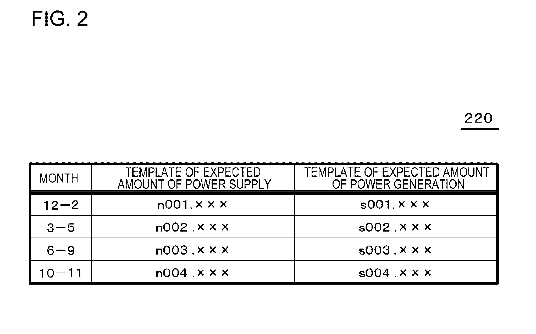
[0070]The history storage unit 230 acquires history data of each of the amount of power supply by the power supply unit 110 from the power supply unit 100 and the amount of power generation by the power generation unit 160 from the power generation unit 160, and stores the history data. The template generation unit 240 periodically generates the template data of each of the amount of power supply and the amount of power generation on the basis of the history data stored in the history storage unit 230, and updates the template data stored in the template storage unit 220. The template generation unit 240 generates a template, for example, by aver...

third embodiment

[0072]FIGS. 10 to 13 are flow charts for explaining the process performed by a quick charging system according to a third embodiment. Since the functional configuration of the quick charging system according to the present embodiment is the same as that in the first or second embodiment, explanation thereof will not be repeated. In the present embodiment, the control unit 210 of the control device 200 of the quick charging system sets a power supply interruption time zone in advance, in which the supply of electrical power is interrupted. In addition, the control unit 210 sets the power supply interruption time zone when insufficiency of the amount of the stored electrical power of the storage battery 120 is expected. In addition, the control unit 210 performs a process of reducing the length of the power supply interruption time zone when insufficiency of the amount of the stored electrical power of the storage battery 120 is expected. Hereinafter, an example of the process will be...


PUM


Abstract

A control device (200) calculates, on the basis of the transition of the expected amount of power generation of a power generation unit (160), the transition of the expected amount of power supply of a power supply unit (110), and the current amount of stored electrical power of a storage battery (120), a transition of the expected amount of the stored electrical power of the storage battery (120) in a case where electrical power continues to be supplied from a power distribution network (300) to the storage battery (120). In addition, the control device (200) sets a power reduction time zone, which is a time zone in which no electrical power is supplied from the power distribution network (300) to the storage battery (120), when the presence of a first time, which is a time when the expected amount of the stored electrical power starts to exceed the first reference capacity, is shown in the transition of the expected amount of the stored electrical power of the storage battery (120), and sets the end time of the power reduction time zone as the first time.

Description

TECHNICAL FIELD[0001]The present invention relates to a quick charging system that supplies electrical power stored in a storage battery to a battery of another apparatus, a control device, a method of controlling the amount of the stored electrical power, and a program.BACKGROUND ART[0002]In recent years, electrical vehicles have been developed in order to reduce the impact on the environment. Meanwhile, in order to spread the use of electrical vehicles, it is necessary to develop a power station to supply electrical power to electrical vehicles. On the other hand, in order to reduce the load on the environment, taking advantage of recycling energy, such as solar power generation, has been in demand.[0003]Patent Document 1 discloses storing electrical power by solar power generation and wind power generation and charging the storage battery of an electrical vehicle using the stored electrical power.RELATED DOCUMENTPatent Document[0004][Patent Document 1] Japanese Unexamined Patent ...

Claims


Application Information

Patent Timeline
Patent Type & Authority Applications(United States)
IPC IPC(8): H02J7/00
CPCH02J7/0054H01M2010/4271H01M10/46H02J1/14H02J3/32H02J7/35B60L2210/10B60L2210/30B60L2240/70Y02T90/16Y02T10/92Y02T90/14B60L53/14B60L53/53Y02T10/70Y02T10/7072Y02T10/72Y02T90/12Y02E60/10H02J2310/48H02J7/00H01M10/44Y04S10/126H02J7/342Y02E60/00
Inventor UENO, SATOSHITADOKORO, YUKARIFUJITA, TAKESHI
Owner NEC CORP
Learn More