
Gas sensor

a technology of gas sensor and sensor body, which is applied in the field of gas sensor, can solve the problems of reduced oxygen concentration in the reference gas in the surroundings of the reference electrode, insufficient oxygen pump,

Active Publication Date: 2020-06-18
NGK INSULATORS LTD
View PDF7 Cites 0 Cited by
  • Summary
  • Abstract
  • Description
  • Claims
  • Application Information

AI Technical Summary

Benefits of technology

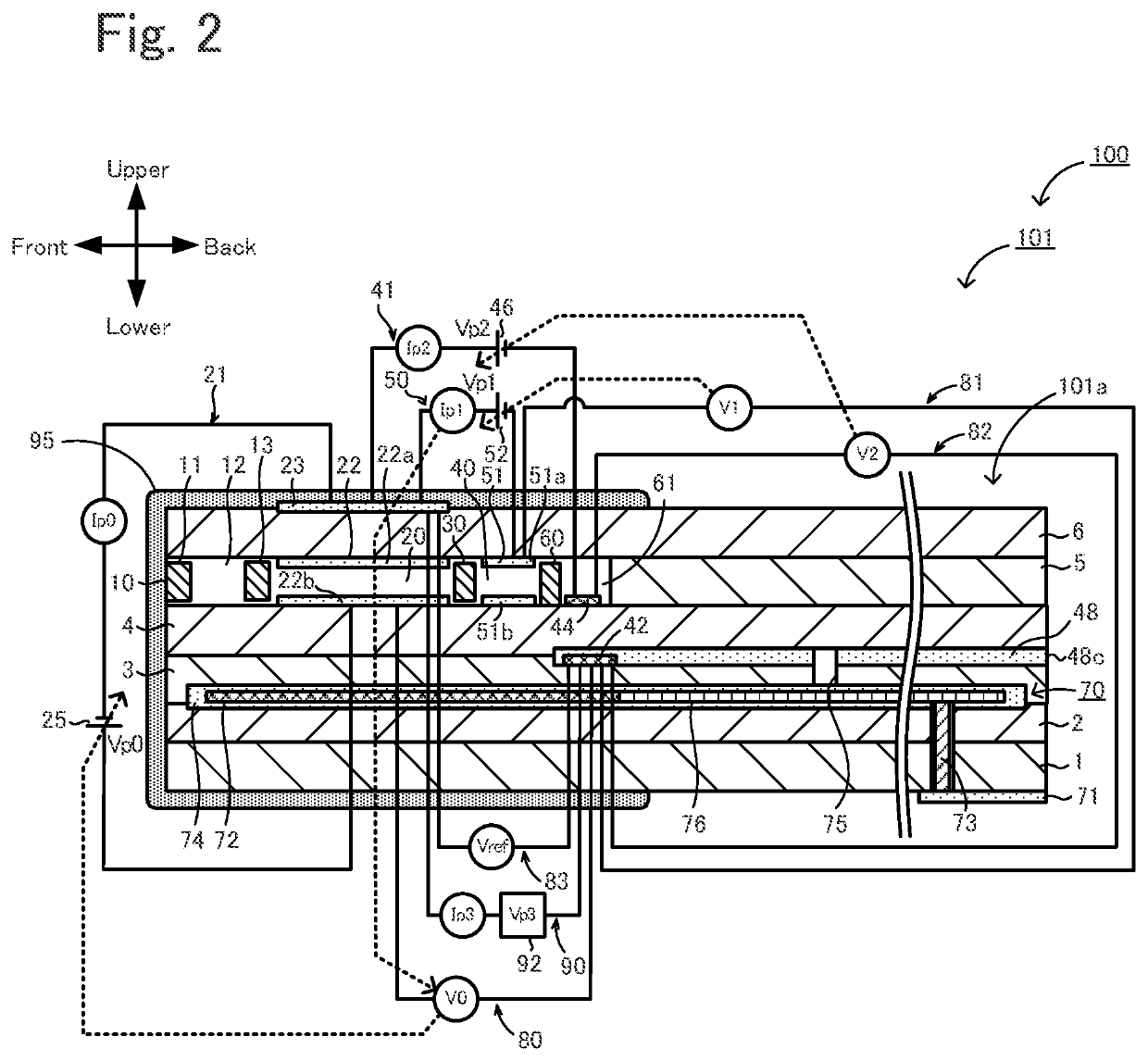
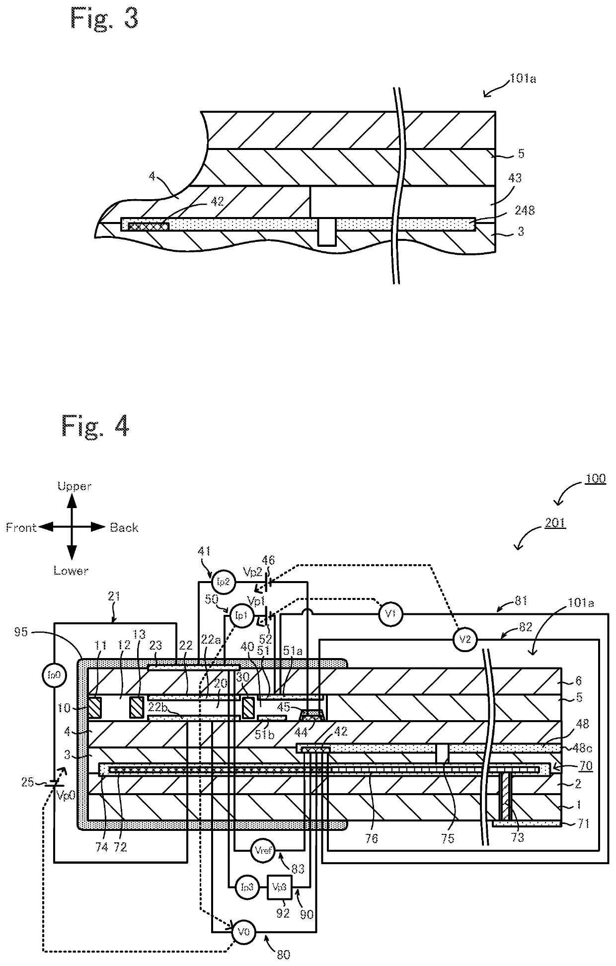
The present invention is aimed at solving the problem of reducing oxygen concentration in the surroundings of the reference electrode in a gas sensor. The invention proposes a gas sensor with a ratio A / B between 125 and 128, which prevents an excessive accumulation of oxygen pumped into the reference electrode's surroundings and ensures appropriate oxygen pumping current. The gas sensor also has an area C and an area D for the measurement-object gas-side electrode and reference electrode, respectively. The ratio C / D should be between 1 and 20 to achieve optimal oxygen pumping. The gas sensor with these features can accurately measure the amount of oxygen in the reference gas.

Problems solved by technology

However, even when the oxygen in the surroundings of the measurement-object gas-side electrode is pumped into the surroundings of the reference electrode, the amount of oxygen pumped may be insufficient, and the oxygen concentration in the reference gas in the surroundings of the reference electrode may be reduced.

Method used


Image

  • Gas sensor
  • Gas sensor
  • Gas sensor

Examples


embodiment

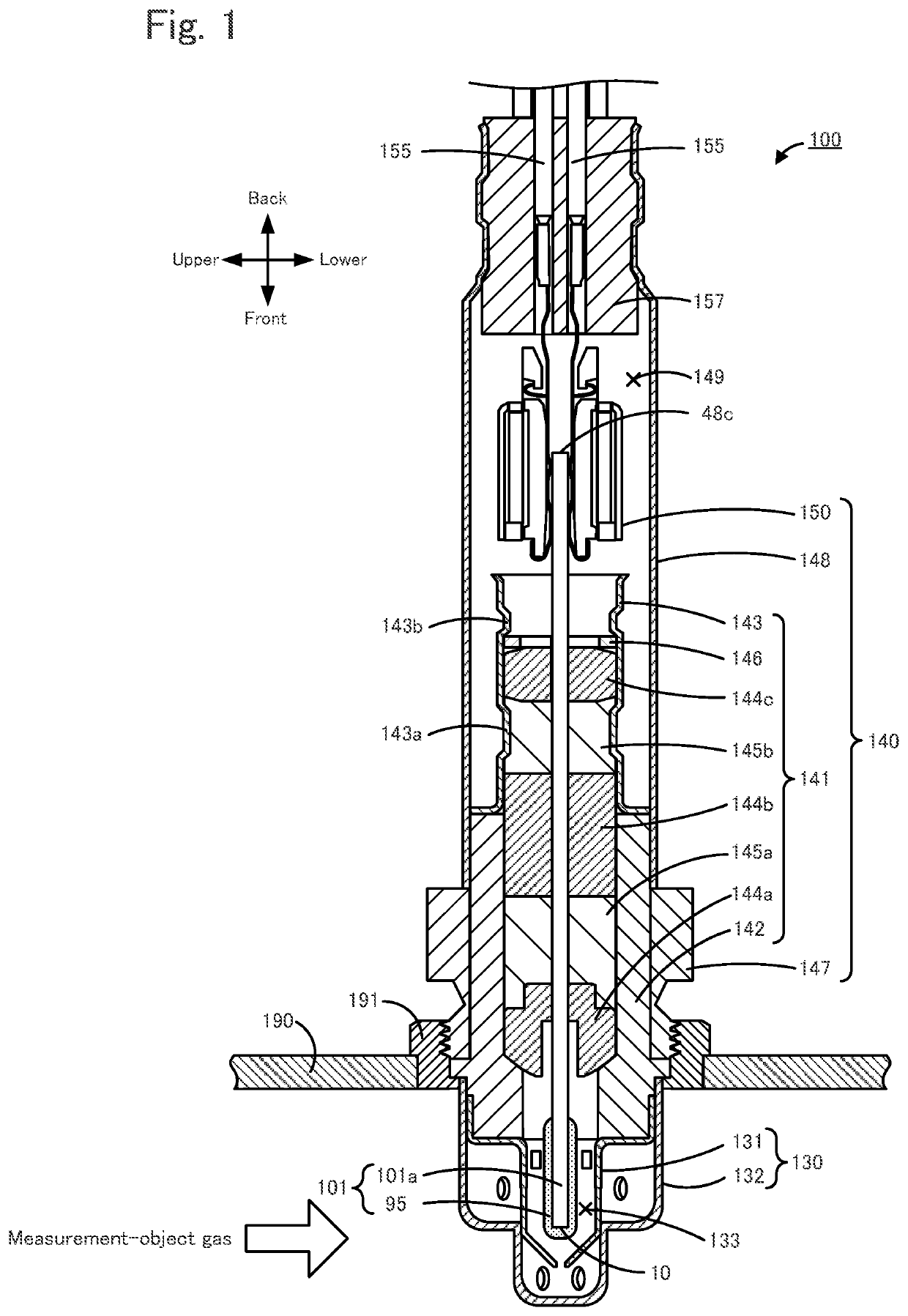
[0111]Hereinafter an example in which the gas sensor is specifically manufactured will be described as an embodiment. It is to be noted that the present invention is not limited to the embodiment below.

experimental example 1

[0112]The gas sensor 100 illustrated in FIGS. 1, 2 was manufactured by the above-described manufacturing method, which is named as experimental example 1. When the sensor device 101 was manufactured, zirconia particles with 4 mol % of yttria serving as a stabilizing agent added, an organic binder, and an organic solvent were mixed, and the green sheets were formed by tape casting. The green pellets 145a, 145b of FIG. 1 were obtained by molding talc particles. The porous protective layer 95 and the air introduction layer 48 are alumina porous materials. The porous protective layer 95 was formed by plasma spraying. The degrees of porosity of the porous protective layer 95 and the air introduction layer 48 were each 20%. The area C of the outer side pump electrode 23 was set to 7.50 mm2, and the area D of the reference electrode 42 was set to 1.85 mm2. The ratio C / D was 4.05. The thicknesses of the outer side pump electrode 23 and the air introduction layer 48 were each 20 μm. When the...

experimental examples 2 to 11

[0113]The gas sensor 100 was produced in the same manner as in Experimental Example 1 except that the limiting currents A, B were set as illustrated in Table 1, and Experimental Examples 2 to 11 were obtained.


PUM

PropertyMeasurementUnit
areaaaaaaaaaaa
areaaaaaaaaaaa
porosityaaaaaaaaaa

Abstract

A gas sensor includes an element body having an oxygen ion conductive solid electrolyte layer and internally provided with a measurement-object gas flow section that introduces a measurement-object gas and allows the gas to flow; a measurement-object gas-side electrode disposed in a portion of the element body, the portion being exposed to the measurement-object gas; and a reference electrode disposed inside of the element body. Let A [μA] be a limiting current when oxygen is pumped from the surroundings of the measurement-object gas-side electrode to the surroundings of the reference electrode with the measurement-object gas introduction section, and B [μA] be a limiting current when oxygen is pumped from the surroundings of the reference electrode to the surroundings of the measurement-object gas-side electrode with the reference gas introduction section, then a ratio A / B is greater than or equal to 0.005.

Description

[0001]The present application claims priority from Japanese Patent Application No. 2018-232677 filed on Dec. 12, 2018, the entire contents of which are incorporated herein by reference.BACKGROUND OF THE INVENTION1. Field of the Invention[0002]The present invention relates to a gas sensor.2. Description of the Related Art[0003]A conventional gas sensor has been known which detects a concentration of a specific gas such as NOx in a measurement-object gas, such as exhaust gas of automobiles. For instance, PTL 1 describes a gas sensor including: a layered body in which multiple oxygen ion conductive solid electrolyte layers are layered; a reference electrode which is formed inside of the layered body and into which a reference gas is introduced from reference gas introduction space; a measurement electrode disposed in a measurement-object gas flow section inside of the layered body; and a measurement-object gas-side electrode disposed in a portion of the layered body, the portion being ...

Claims


Application Information

Patent Timeline
Patent Type & Authority Applications(United States)
IPC IPC(8): G01N27/407G01N27/419G01N27/41G01N27/409G01N27/30
CPCG01N27/4077G01N27/301G01N27/419G01N27/41G01N27/4073G01N27/4072G01N27/409G01N27/4074G01N27/4078G01N27/4067Y02A50/20
Inventor WATANABE, YUSUKE
Owner NGK INSULATORS LTD
Learn More