Magnetic-Resonance Transceiver-Phased Array that Compensates for Reactive and Resistive Components of Mutual Impedance between Array Elements and Circuit and Method Thereof

a phased array and array element technology, applied in the field of decoupling methodologies and circuits thereof, can solve the problems of increasing rf inhomogeneity, limiting the obtainable decoupling by as much as 10 db, and affecting the sensitivity of the array elemen

Active Publication Date: 2013-10-17
TRANSARRAY
View PDF0 Cites 17 Cited by
  • Summary
  • Abstract
  • Description
  • Claims
  • Application Information

AI Technical Summary

Problems solved by technology

With a large number of small interacting antennas, decoupling is one of the most challenging aspects in the design and construction of transceiver arrays.
These decoupling methods may limit the obtainable decoupling by as much as −10 dB due to residual mutual resistance.
At high magnetic field strengths, where the object size becomes comparable to the RF wavelength, increased RF inhomogeneity, decreased transmit efficiency (μT / √W), and increasing local specific absorption rate (SAR) pose significant limitations for conventional single-channel transmit volume coils.
Thus, at high magnetic field, it has been observed that a performance of a single transmission coil is significantly limited by increased RF inhomogeneity, decreased transmit efficiency (μT / W), and increased local specific absorption rate (SAR).
The interaction is referred to as cross-talk and affects the RF field profile of the array, thus degrading the array transmission and reception performance, thereby lowering the signal-to-noise ratio (SNR) of the transceiver phased array.
With a large number of interacting RF antennas decoupling, i.e. eliminating the cross talk, is becoming one of the most challenging and critical aspects in designing and constructing transceiver phased arrays.
Therefore, in these cases, use of any previously described decoupling schemes does not provide a complete decoupling of the array elements.
However, the placement and the geometry of these RID elements are critical since the RF field generated by the RID can significantly alter the RF field of the array.

Method used


Image

  • Magnetic-Resonance Transceiver-Phased Array that Compensates for Reactive and Resistive Components of Mutual Impedance between Array Elements and Circuit and Method Thereof
  • Magnetic-Resonance Transceiver-Phased Array that Compensates for Reactive and Resistive Components of Mutual Impedance between Array Elements and Circuit and Method Thereof
  • Magnetic-Resonance Transceiver-Phased Array that Compensates for Reactive and Resistive Components of Mutual Impedance between Array Elements and Circuit and Method Thereof

Examples


Embodiment Construction

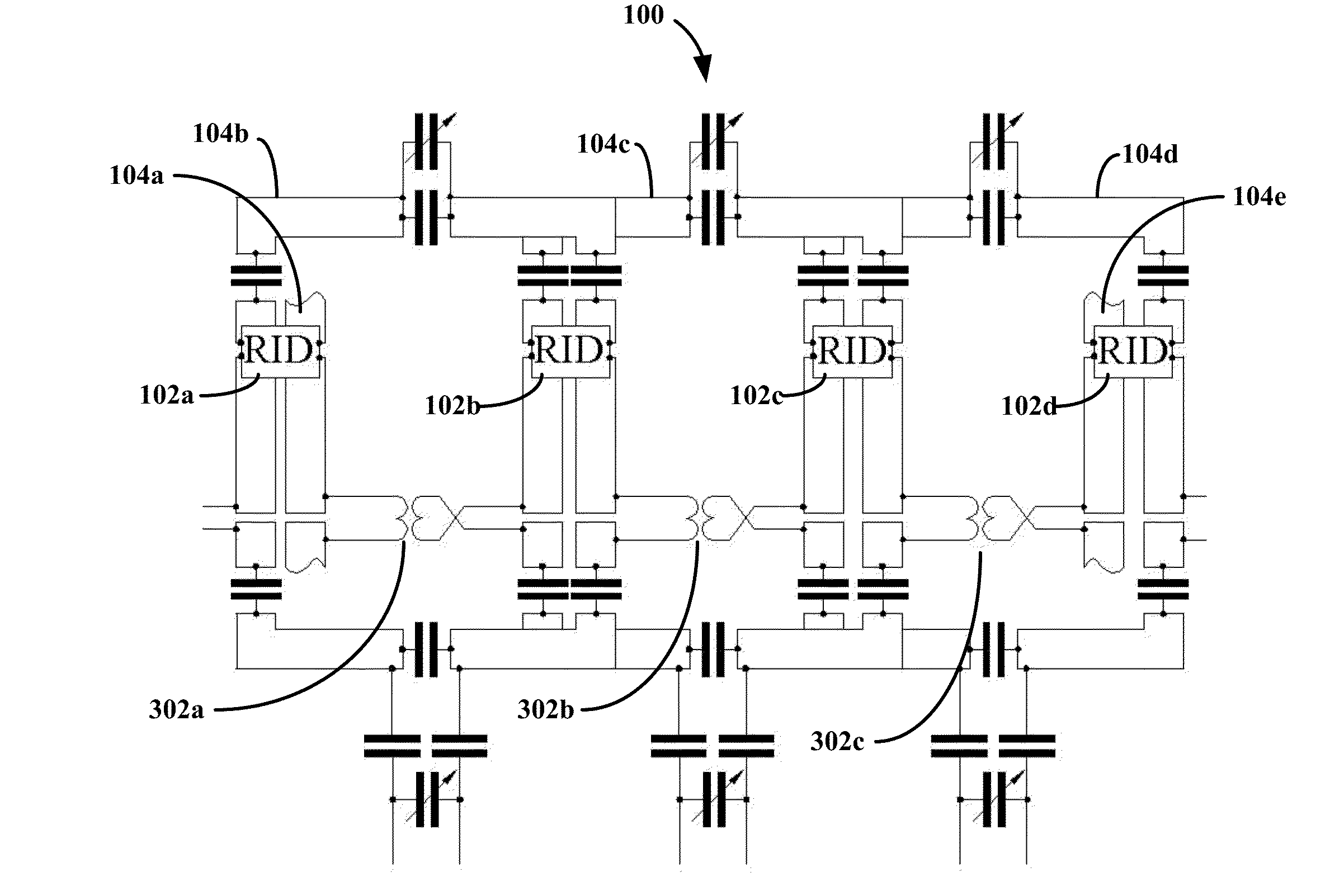
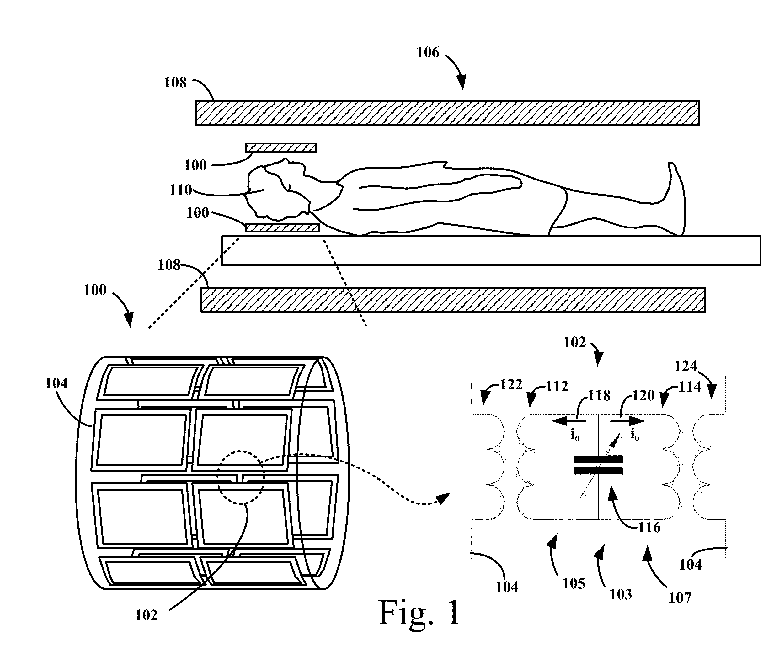
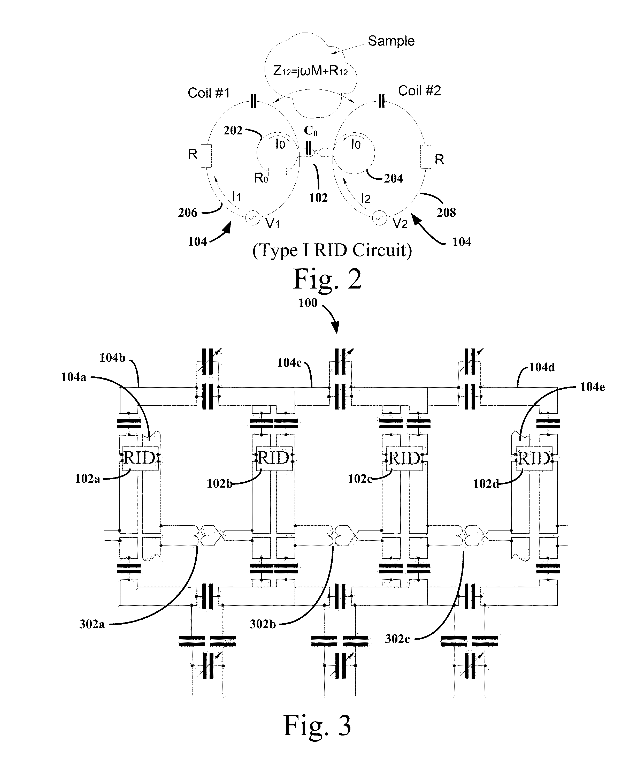
[0020]In a first embodiment of the invention, there is provided a novel method of compensating for cross-talk between pairs of adjacent array elements of a transceiver phased array for a magnetic resonance (MR) system. The transceiver phased array includes array elements circumscribing a sample. In an embodiment, a method of operating a transceiver phased array decoupled using the illustrative embodiment is provided. The transceiver phased array is operated in the MR system to produce a dataset of the sample. The dataset may be used to derive (i) an image using various described MR imaging modalities or (ii) spectroscopic data using various measurement modalities described herein. The transceiver array elements, i.e. RF antennas, may be configured as surface coils used for both for transmission and reception of RF signals. During transmission and reception, the pair of array elements has cross-talk characterized as mutual impedance therebetween, which may include both resistive and ...


PUM


Abstract

There is provided a novel method and circuit of compensating for cross-talk between pairs of adjacent array elements of a transceiver phased array and double-tuned transceiver arrays for a magnetic resonance system using a resonant inductive decoupling circuit. The geometry and size of the resonant inductive decoupling circuit allows for the decoupling circuit to compensate for the cross-talk between array elements, including the reactive and resistive components of the mutual impedance while being sufficiently small to not distort a RF magnetic field of the array elements produced within a sample.

Description

PRIORITY[0001]The present application claims priority from Provisional Application No. 61 / 625,196 filed Apr. 17, 2012, titled “Resonant Inductive Decoupling for MRI Transceiver Phased Arrays to Compensate for both Reactive and Resistive Components of the Mutual Impedance.” The application is incorporated by reference herein in its entirety.GOVERNMENT RIGHTS[0002]This invention was made with government support under Contract no. EB009871 and Contract No. EB011639 awarded by the National Institute of Health. The government has certain rights in the invention.TECHNICAL FIELD[0003]The present invention relates to decoupling methodologies and circuits thereof for array elements of a magnetic-resonance transceiver phased array, and more particularly to compensate for cross-talk among the array elements using a resonant inductive decoupling circuit.BACKGROUND ART[0004]Transceiver phased arrays (also referred to as transceiver surface-coil arrays) may improve transmission performance (B1 / √k...

Claims


Application Information

Patent Timeline
Patent Type & Authority Applications(United States)
IPC IPC(8): G01R33/36
CPCG01R33/3642G01R33/3415G01R33/3635G01R33/365
Inventor AVDIEVICH, NIKOLAI I.HETHERINGTON, HOBY P.PAN, JULLIE W.
Owner TRANSARRAY
Why Eureka
Try Eureka