
N-path filter with coupling between paths

a filter circuit and path technology, applied in the field of electric circuits, can solve the problems of reducing the sensitivity of component variations, complex sampling analog filters, and achieving high-q filters with a high f/sub>s,

Inactive Publication Date: 2013-10-17
KABEN WIRELESS SILICON
View PDF1 Cites 3 Cited by
  • Summary
  • Abstract
  • Description
  • Claims
  • Application Information

AI Technical Summary

Benefits of technology

The present invention is an N-path filter with each path filter comprising a substantially identical filter. The filter can be designed to shift poles and zeros to different frequency offsets from fs / N. The filter can be implemented using digital filters and also using memory capacitors and rotating capacitors for cross-coupling between paths. The technical effects of this invention include the ability to filter signals effectively with a minimum number of components and the use of a rotating capacitor for signal output, which reduces the number of components required.

Problems solved by technology

Further, conventional sampled analog filters can be complex, in which two parallel (possibly differential) signals, representing simultaneous quadrature components of a complex signal, are filtered.
While polyphase filters may not provide any filtering capability over that of a complex filter, they do provide reduced sensitivity to component variations.
Achieving a high-Q filter with a high fs has been found difficult in the past.
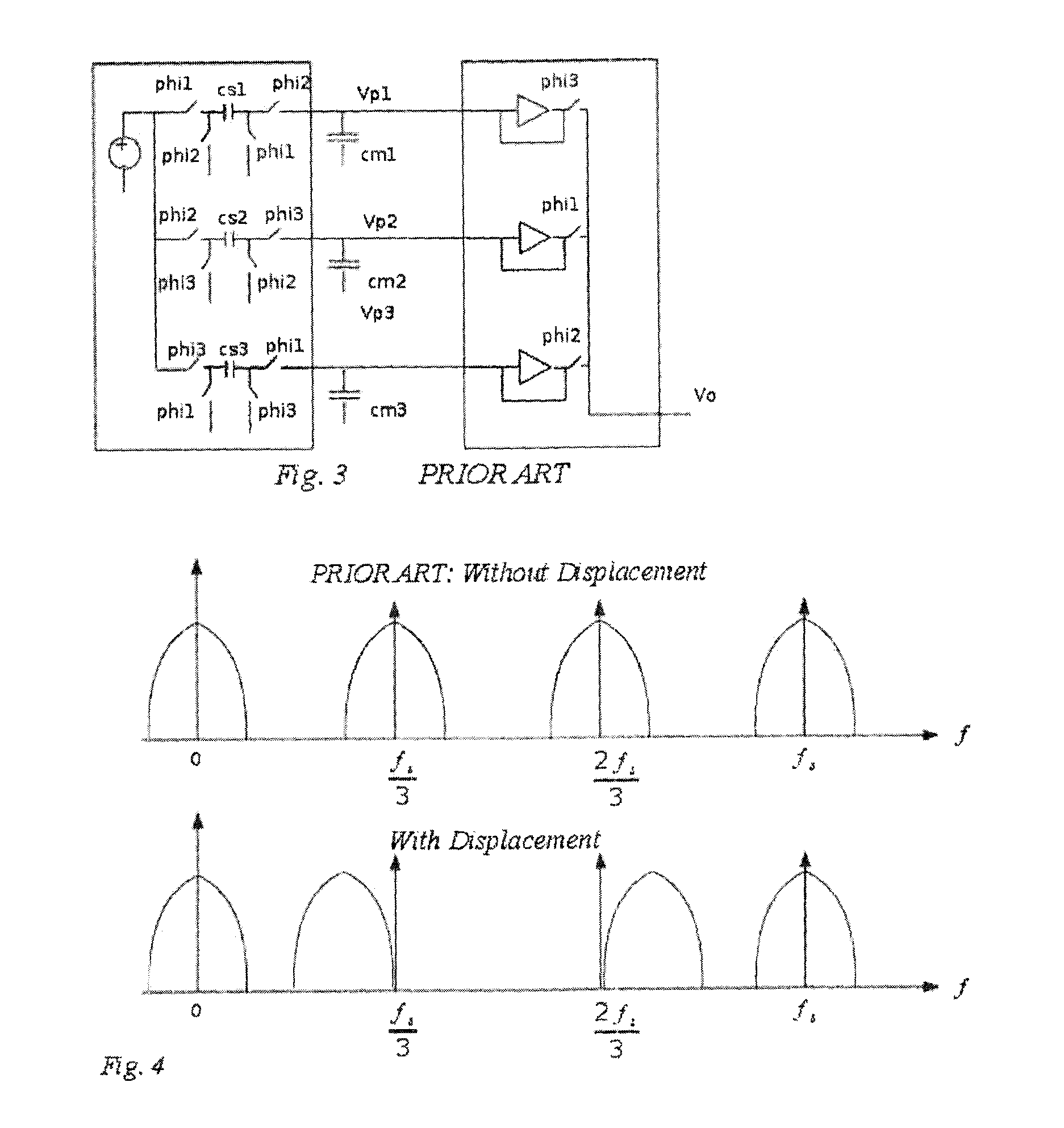
The above constraint that each path is clocked at fs / N results in a major difficulty of the N-Path filter that, for a given sampling rate fs, copies of the desired filter pass-band exist at frequencies corresponding to all multiples of fs / N.
The multiple pass bands can be inconvenient if blocking signals could occur at these frequencies.
Another problem that may be encountered is that the clocks for the filter, as well as dc offsets, mismatches, and other impairments, tend to create spurious tones at multiples of fs / N.
However, the problem of clock feed-through, centered at the desired frequency-multiple of fs / N cannot be removed unless a notch is inserted in the pass-band, which will affect the desired signal if the signal has desired information spectrally close to fs / N.

Method used


Image

  • N-path filter with coupling between paths
  • N-path filter with coupling between paths
  • N-path filter with coupling between paths

Examples


Embodiment Construction

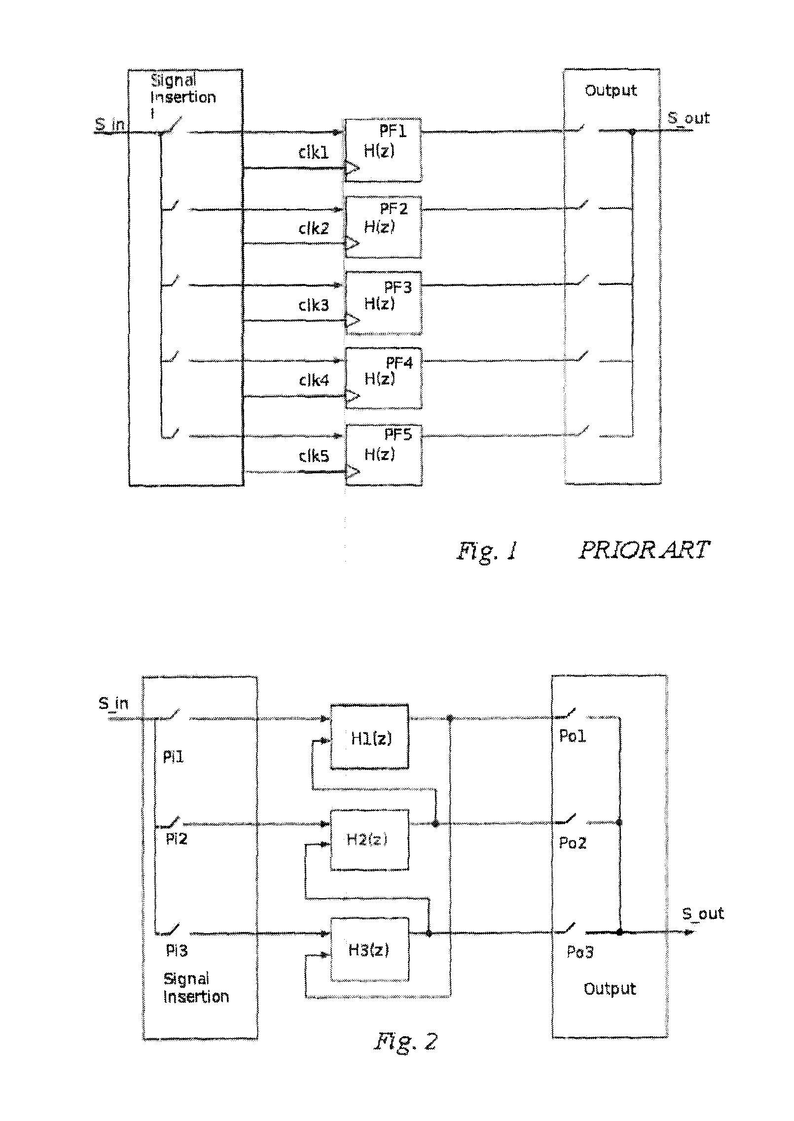
[0029]As can be seen from FIG. 1, an N-path filter according to the prior art has, at the leftmost portion of the circuit, a signal insertion block which periodically inserts signal into each path in the properly interleaved sequential order. Many of these signal insertion blocks are described in the N-path literature and known to those versed in the art. For this circuit, the filter produces an output out from an input in every 10 ns (corresponding to an fs of 100 MHz). Each of the path filters PF1 to PF5 is clocked at 20 MHz with clock phases which make the path filters sequentially responsive to a signal S_in. The signal insertion block provides clock phases, clk1 to clk5 such that clk2 is delayed from clk1 by 10 ns. Similarly each of clocks clk3 to clk4 is delayed by 10 ns relative to the previous clock for a total delay of 40 ns for clk4. As a result, clk1 is also delayed by 10 ns from its previous clock clk4. As part of the signal insertion block, clock generators generate con...


PUM


Abstract

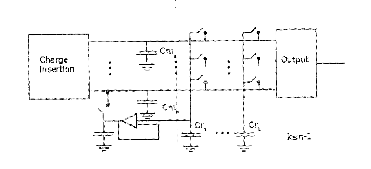
An N-path filter with each path forming a different filter. A signal insertion block is provided at the start of the circuit and, in one embodiment, multiple memory capacitors are coupled to the signal insertion block. A bank of sequential rotating capacitors are provided along with a bank of switches. By activating selected switches, any of the memory capacitors can be coupled to selected rotating capacitors. A different filter subcircuit is formed by coupling each memory capacitor to different rotating capacitors as this creates a different signal path. By timing the switching of the rotating capacitors, signals from previous outputs can be inserted into the circuit. At the output end of the circuit, the output of the different filter subcircuits is put together into an output for the whole circuit.

Description

TECHNICAL FIELD[0001]The present invention relates to electrical circuits. More specifically, the present invention relates to an N-Path filter circuit in which each path filter through the circuit forms a substantially identical filter.BACKGROUND OF THE INVENTION[0002]Sampled analog filters are described mathematically the same way as digital filters; the difference is that the time-sampled signal is represented as a an analog signal such as a charge or a voltage in switched capacitor circuits or as a current in switched current or charge-domain filters whereas in a digital filter the time-sampled signal is represented as a quantized number.[0003]A conventional sampled analog filter can be single ended, having one path. In the conventional analog filter, a charge is collected on a capacitor forming a first part of the filter circuit through an input switch, and is then transferred to other capacitors forming other parts of the filter circuit through other switches and operational a...

Claims


Application Information

Patent Timeline
IPC IPC(8): H03H11/04H03H7/01
CPCH03H11/04H03H7/0138H03H19/002
Inventor RILEY, THOMAS
Owner KABEN WIRELESS SILICON
Learn More