
Method of driving a display device

a display device and display screen technology, applied in the field of display device driving, can solve the problems of standard charging time, inability to gurantee enough time to charge the liquid crystal, and longer light providing time of the backlight unit, so as to enhance the total luminance of the screen, reduce the delay time of pixel rows, and reduce the effect of delay tim

Inactive Publication Date: 2013-10-17
SAMSUNG DISPLAY CO LTD
View PDF3 Cites 7 Cited by
  • Summary
  • Abstract
  • Description
  • Claims
  • Application Information

AI Technical Summary

Benefits of technology

The present invention provides a method for driving a display device that reduces frame scanning delay time within a limited response time. This is achieved by simultaneously charging at least two pixel rows, which results in a delay time for each frame. By doing so, a 3D image can be displayed without decreasing the vertical resolution. Additionally, the effective charging interval is longer, which enhances the total luminance of the screen and reduces manufacturing costs. Thus, the invention improves the display quality and reduces manufacturing costs.

Problems solved by technology

As a result, it is impossible to gurantee enough time to charge the liquid crystal when the standard charging time is too long.
Moreover, an effective charging interval that a charging of the liquid crystal cells is completed in each frame is longer than a conventional art, so that a light providing time of a backlight unit may be longer.

Method used


Image

  • Method of driving a display device
  • Method of driving a display device
  • Method of driving a display device

Examples


Embodiment Construction

[0067]Hereinafter, exemplary embodiments of the present invention will be explained in detail with reference to the accompanying drawings.

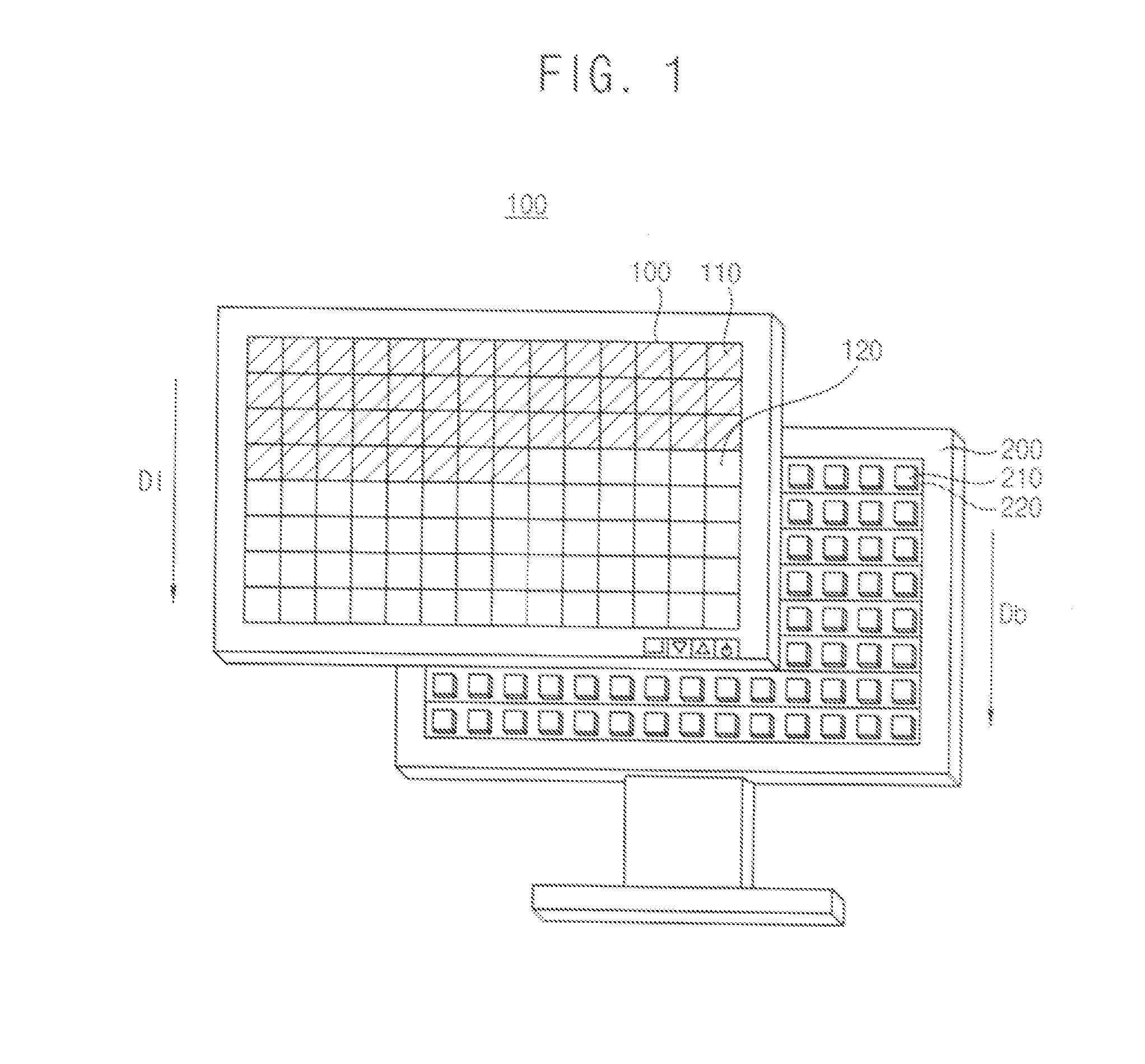
[0068]FIG. 1 is a perspective view schematically explaining an operation of a display device.

[0069]Referring to FIG. 1, a display device includes a liquid crystal display panel 100 and a backlight unit 200. The liquid crystal display panel 100 includes a plurality of liquid crystal cells 110 and 120. The backlight unit 200 includes a plurality of light source substrate 220 and a plurality of light sources 210 formed on the light source substrate 220. The light sources 210 in FIG. 1 are light-emitting diodes (LED). The light sources 210 may be an electro luminescence (EL), a cold cathode fluorescent lamp (CCFL), a hot cathode fluorescent lamp (HCFL), an external electrode fluorescent lamp (EEFL), etc.

[0070]In order to display an image on the liquid crystal panel 100, voltages according to each image pixel are applied to the liquid crystal cells 110...


PUM


Abstract

A method of driving a display device includes a preliminary frame charging step and a main frame charging step. The method comprises a preliminary frame charging step of simultaneously charging liquid crystal cells in a pixel line group having a selected pixel row and a unselected pixel row with pixel data of the selected pixel row of the pixel line group and a main frame charging step of charging liquid crystal cells in the unselected pixel line group with pixel data of the unselected pixel line group.

Description

CROSS-REFERENCE TO RELATED APPLICATIONS[0001]This application claims priority under 35 U.S.C. §119 to Korean Patent Application No. 10-2012-0039317, filed on Apr. 16, 2012 in the Korean Intellectual Property Office (KIPO), the contents of which are herein incorporated by reference in their entirety.BACKGROUND OF THE INVENTION[0002]1. Technical Field[0003]Exemplary embodiments of the present invention relate to a method of driving a display device. More particularly, exemplary embodiments of the present invention relate to a method of driving a display device for reducing a frame scanning delay.[0004]2. Discussion of the Related Art[0005]A liquid crystal display device displays images by controlling a light transmittance using liquid crystals which change transmittance of light according to a voltage applied to the liquid crystal. A liquid crystal display device includes a liquid crystal display panel displaying images and a backlight unit providing light to the liquid crystal displa...

Claims


Application Information

Patent Timeline
IPC IPC(8): G09G3/36
CPCG09G3/3696G09G3/003G09G3/3648G09G2310/0205G09G2310/0218G09G2310/0224G09G2310/0227G09G2310/0237G09G2310/024G09G2310/0251G09G2320/0261G09G3/36G02F1/13306G02F1/136286G09G2310/0283G09G2320/0233
Inventor AHN, IK-HYUNPARK, BONG-IMKIM, SEON-KIHUR, SE-HUHN
Owner SAMSUNG DISPLAY CO LTD
Learn More