Method and system for generating a three-dimensional user-interface for an embedded device

a technology of user interface and embedded devices, applied in the field of three-dimensional user interface generation, can solve the problems of lock-in effect and object optimization in this spa

Inactive Publication Date: 2013-10-17
RIGHTWARE
View PDF5 Cites 3 Cited by
  • Summary
  • Abstract
  • Description
  • Claims
  • Application Information

AI Technical Summary

Benefits of technology

[0025]In a further embodiment of the invention, said binary output file is provided in the form of a set of files. In this embodiment, said set of files includes a configuration file, a standalone file and a list of patch files. In this embodiment, said configuration file is provided in a simple format and contains a number of file paths, each of said file paths being relative to a working directory of an application using said configuration file. In this embodiment of the invention, said method further comprises the step of: applying said list of patch files on top of said standalone file so as to create a data container, said data container being operable to be patched further.
[0026]In this embodiment, a patch file in said list of patch files is operable to add, replace and delete one or more assets from said standalone file. In this embodiment of the invention, said patch file is generated by exporting said standalone file, comparing said standalone file to a base file and saving any modifications to said standalone file into a patch file. Here, any temporary standalone data in said base file is discarded.

Problems solved by technology

However, it will be appreciated by those in the industry, that these known systems provide problems with regard to the implementation of the user-interface as well as its differentiation in the three-dimensional domain.
In particular, in terms of these known systems, when changes are effected to an object in a graphical user interface (GUI) on a two-dimensional plane the changes are not translated adequately in the three-dimensional space and the resultant object will therefore not be optimized for viewing in this space.
Furthermore, known systems provide problems for device manufacturers as it results in a lock-in effect, in terms of which the GUI is limited to use on a specific platform or version of an operating system.

Method used


Image

  • Method and system for generating a three-dimensional user-interface for an embedded device
  • Method and system for generating a three-dimensional user-interface for an embedded device
  • Method and system for generating a three-dimensional user-interface for an embedded device

Examples


Embodiment Construction

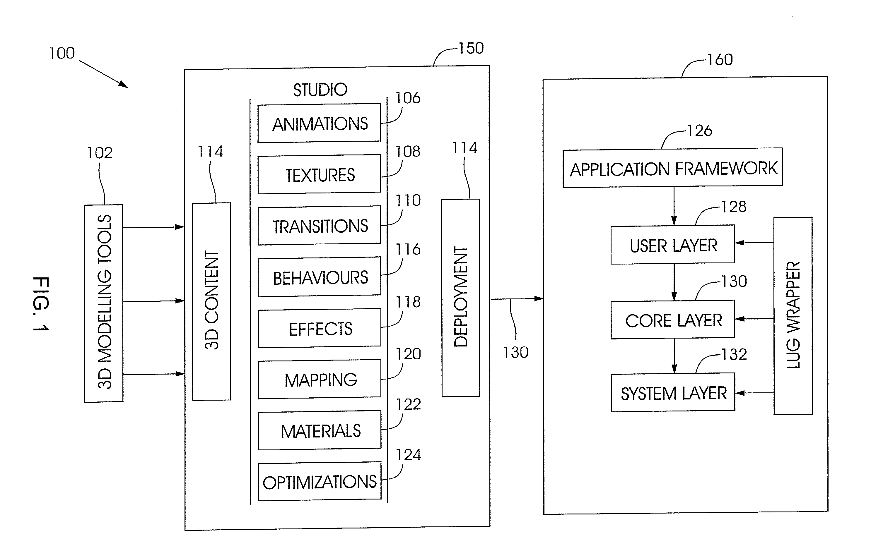
[0041]Referring to FIG. 1 of the drawings, a system for generating a graphical user interface for an embedded device is generally indicated by reference numeral 100.

[0042]The system 100 comprises a design studio 150 on a host device and a graphics engine 160 on a client or end device, the devices being in continuous or selective communication with each other through, for example, the interface 130. Three-dimensional modeling tools 102 feed into the design studio 150 which in turn feeds into the graphics engine 160.

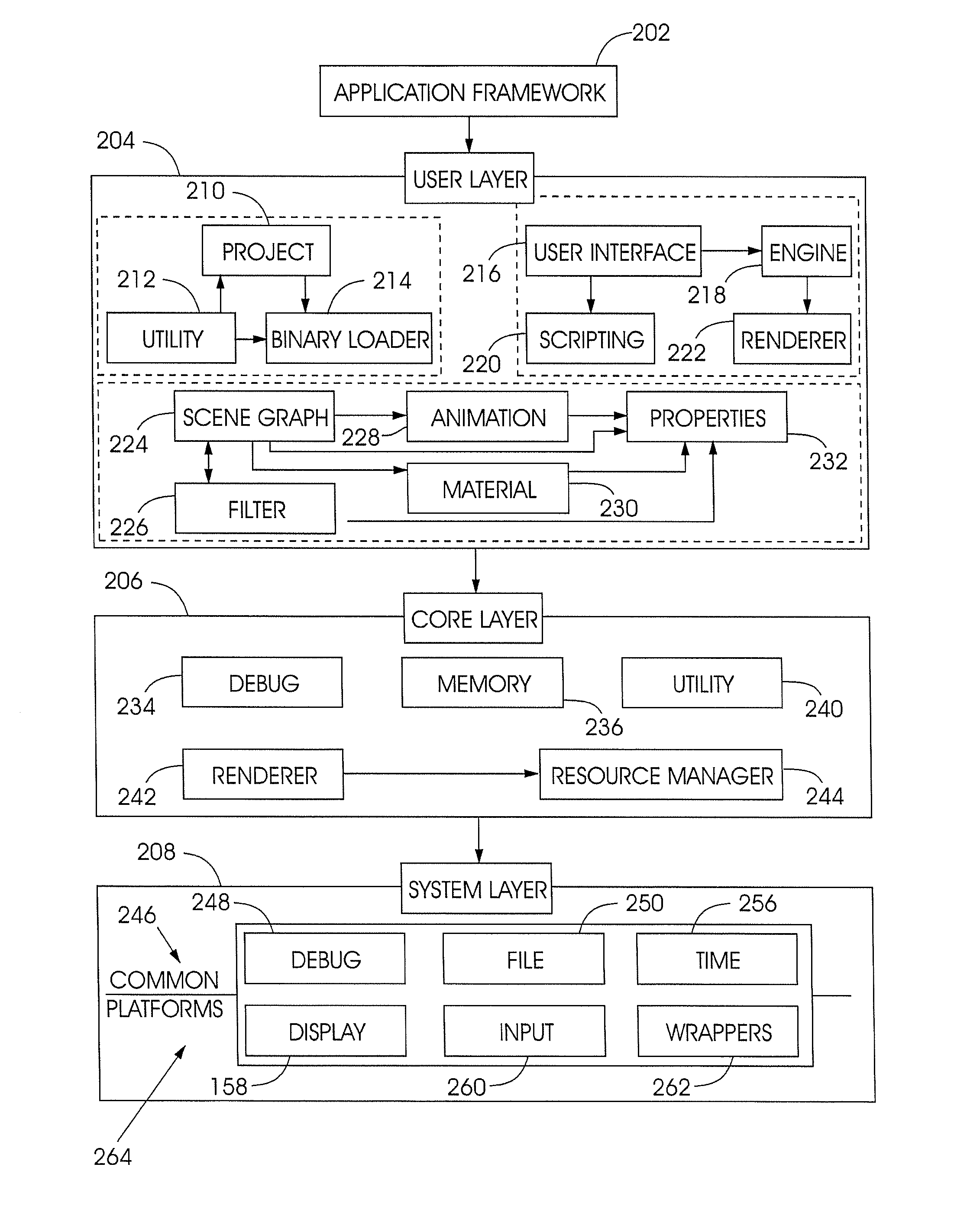
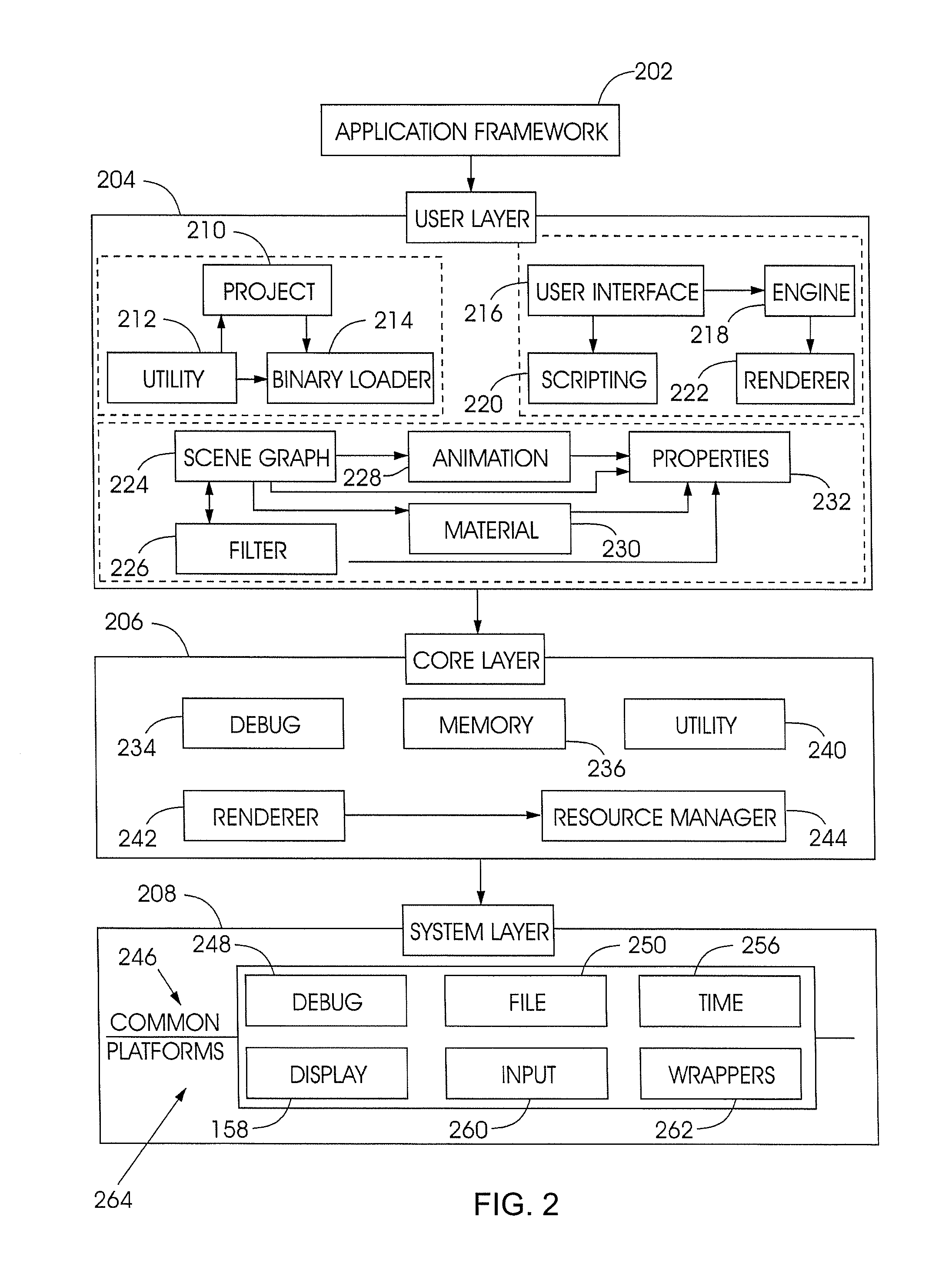
[0043]In this particular depiction of an embodiment of the invention, the system 100 is shown to include a design studio 150 and a graphics engine 160, each of which in more detail includes a plurality of functional components, the design studio 150 including an animation component 106, a textures component 108, a transitions component 110, a behaviors component 116, an effects component 118, a mappings component 120, a materials component 122 and an optimizations compone...


PUM


Abstract

The present invention relates generally to a method and system for generating a three-dimensional user-interface on an embedded device or devices. The method of generating a three-dimensional user interface comprising the steps of importing an asset into an editor on a host device, allowing a user to graphically effect modifications within the editor, modifying at least one property of the asset independently of a user to optimize a three-dimensional generation of the asset on an embedded device, generate a binary output file of the modified asset, and outputting the binary file to a graphics engine. Wherein the graphics engine is operable to load and render files as at least a portion of a graphical user interface its embedded device. Additionally, there is described an ordering of data in the binary output file such that it is independent of a degree of significance of individually accessible data within said output file.

Description

FIELD OF THE INVENTION[0001]This invention relates to a method and system for generating a three-dimensional user interface for at least one embedded device.BACKGROUND TO THE INVENTION[0002]Within the field of application of the present invention, systems have been developed for the development and rendering of a graphical user-interface for use within a three-dimensional space on a mobile or wireless device.[0003]However, it will be appreciated by those in the industry, that these known systems provide problems with regard to the implementation of the user-interface as well as its differentiation in the three-dimensional domain.[0004]In particular, in terms of these known systems, when changes are effected to an object in a graphical user interface (GUI) on a two-dimensional plane the changes are not translated adequately in the three-dimensional space and the resultant object will therefore not be optimized for viewing in this space.[0005]In view of the above, it will be appreciat...

Claims


Application Information

Patent Timeline
Patent Type & Authority Applications(United States)
IPC IPC(8): G06T15/00G06F30/00G06F111/16
CPCG06T15/005G06F8/38
Inventor RUOTSALAINEN, ARTOVOLOTINEN, TUOMASSELL, MIIKALINDQVIST, LASSEVLASOV, ALEXEYLAATIKAINEN, RAULILEHTINEN, JUSSIKOIVU, TEROHELPPI, VILLE-VEIKKO
Owner RIGHTWARE
Why Eureka
Try Eureka