Supercharge Your Innovation With Domain-Expert AI Agents!

Multi-pair differential lines printed circuit board common mode filter

Active Publication Date: 2013-10-17
INTEL CORP
View PDF2 Cites 9 Cited by
  • Summary
  • Abstract
  • Description
  • Claims
  • Application Information

AI Technical Summary

Benefits of technology

The patent text describes a solution for reducing common mode noise in high-speed data links. The invention involves the use of multi-pair differential lines with common mode filtering. The technical effect of this solution is to improve the performance of interconnects in computer systems by reducing common mode noise radiation and improving signal quality. The invention can be applied to various systems and interconnects, such as printed circuit boards and cables. The solution involves using differential signaling to offer advantages over single-ended signaling in high-speed / frequency signaling, particularly in terms of noise immunity. The invention also includes a block diagram of an example interconnect and a plan view of a multi-pair differential line common mode filtering.

Problems solved by technology

With ever increasing data rates, the radio performance can be degraded significantly due to common mode noise radiation from high speed data.

Method used


Image

  • Multi-pair differential lines printed circuit board common mode filter
  • Multi-pair differential lines printed circuit board common mode filter
  • Multi-pair differential lines printed circuit board common mode filter

Examples


Embodiment Construction

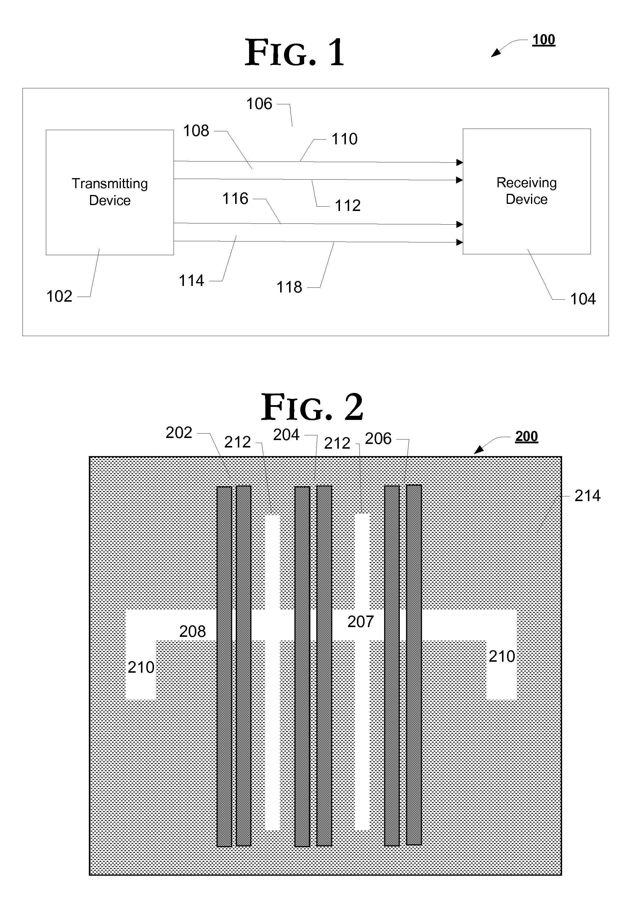
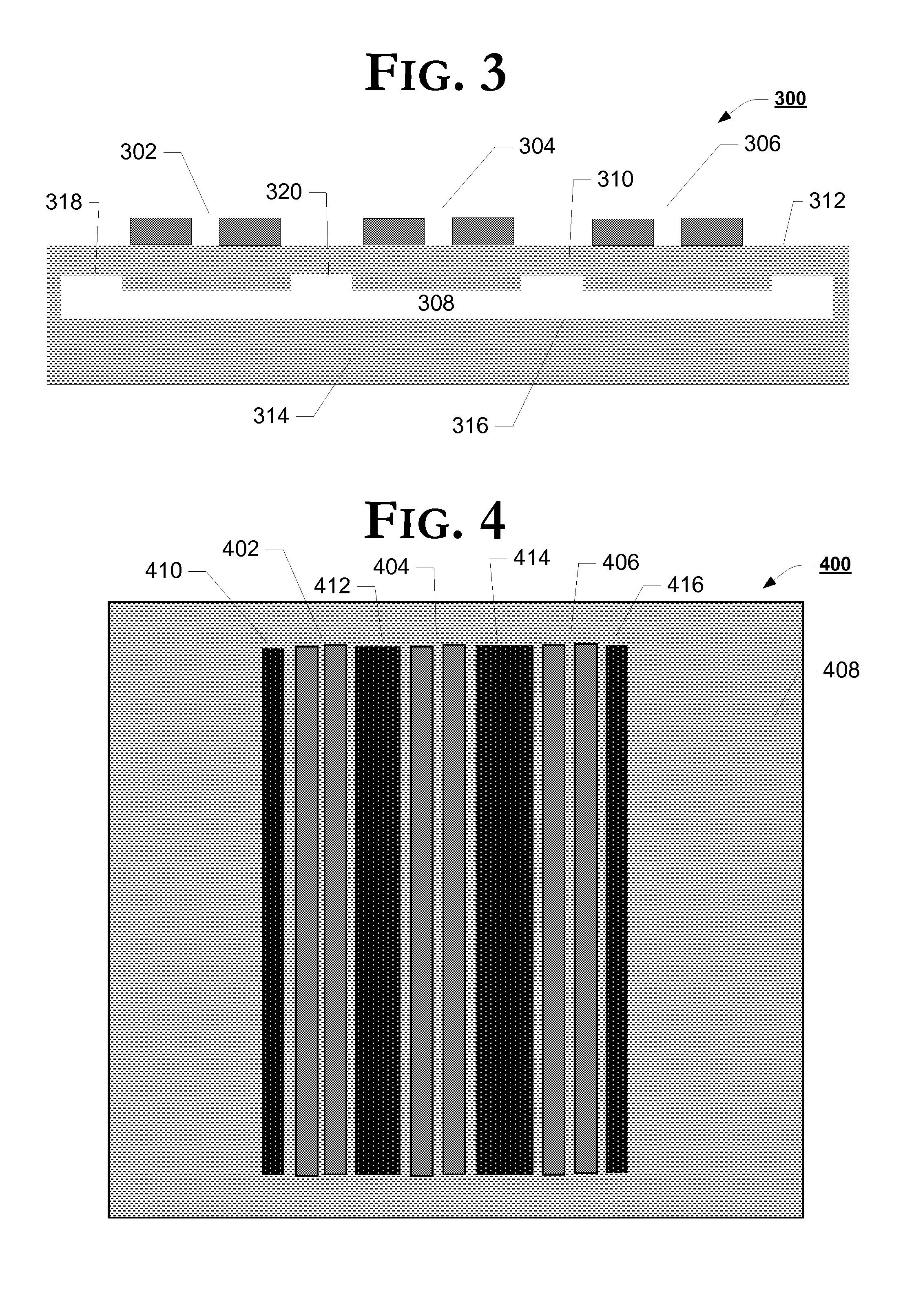
[0010]In the following description, numerous specific details such as logic implementations, sizes and names of signals and buses, types and interrelationships of system components, and logic partitioning / integration choices are set forth in order to provide a more thorough understanding. It will be appreciated, however, by one skilled in the art that the invention may be practiced without such specific details. In other instances, control structures and gate level circuits have not been shown in detail in order not to obscure the invention. Those of ordinary skill in the art, with the included descriptions, will be able to implement appropriate logic circuits without undue experimentation.

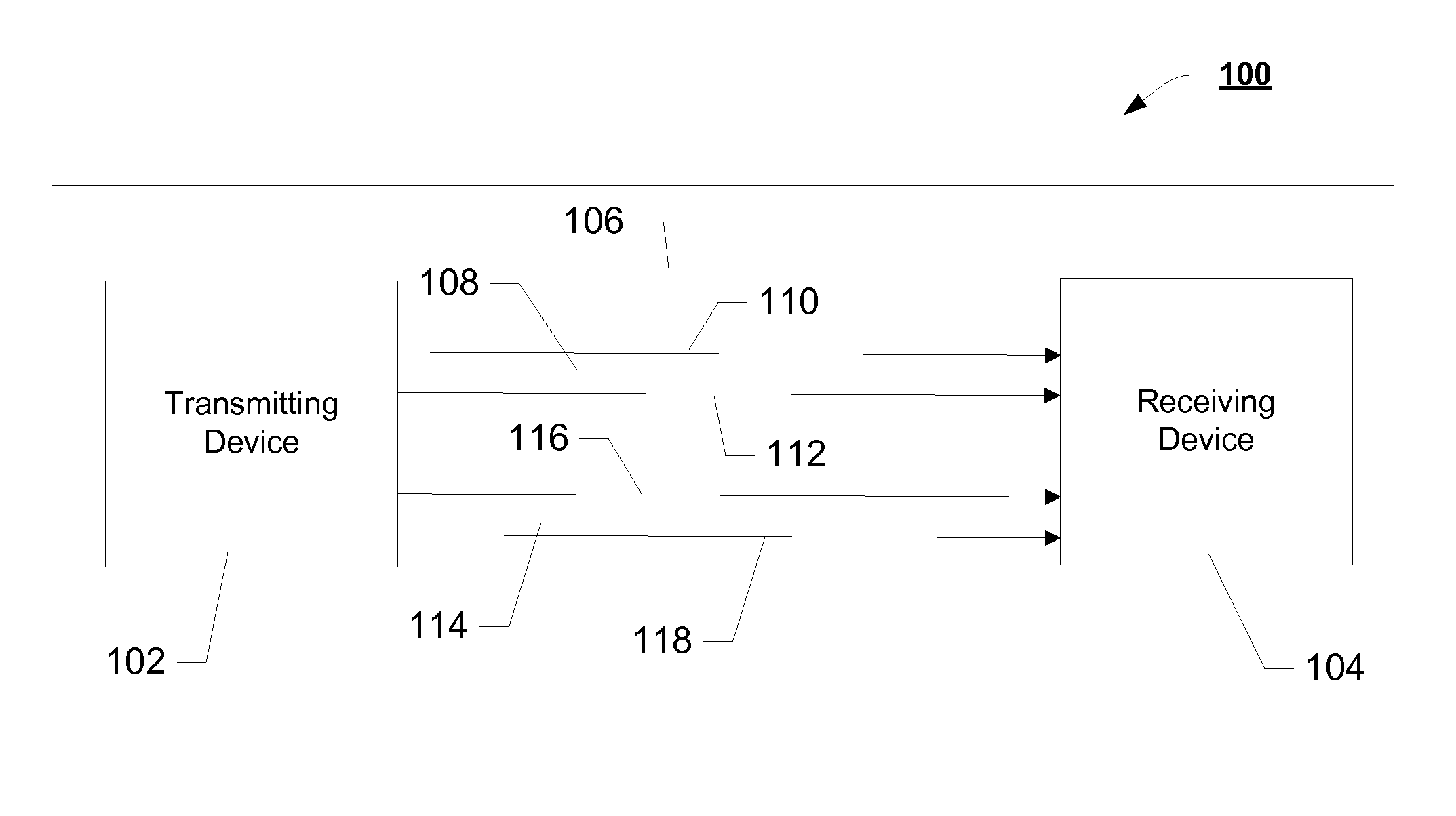
[0011]In addition, although an embodiment described herein is directed to multi-pair differential line common mode filtering, it will be appreciated by those skilled in the art that the embodiments of the present invention can be applied to other systems. Other structures may fall within the embod...


PUM


Abstract

Multi-pair differential lines printed circuit board common mode filters are generally described. In one embodiment, the apparatus includes a multi-layer printed circuit board, a first signal line and a second signal line forming a first differential pair on a first layer of the printed circuit board, a second differential pair on the first layer of the printed circuit board, and a common mode filter on a second layer of the printed circuit board, the common mode filter comprising an absence of a predominantly occurring dielectric material of the printed circuit board, the common mode filter spanning an area directly below at least a portion of both the first and the second differential pairs. Other embodiments are also described and claimed.

Description

FIELD OF THE INVENTION[0001]One or more embodiments of the invention relate generally to the field of interconnect. More particularly, one or more of the embodiments of the invention relates to multi-pair differential lines printed circuit board common mode filter.BACKGROUND OF THE INVENTION[0002]Communication between devices within a computer system may involve high speed / frequency data links. With ever increasing data rates, the radio performance can be degraded significantly due to common mode noise radiation from high speed data.BRIEF DESCRIPTION OF THE DRAWINGS[0003]The various embodiments of the present invention are illustrated by way of example, and not by way of limitation, in the figures of the accompanying drawings and in which:[0004]FIG. 1 is a block diagram of an example interconnect, in accordance with one example embodiment of the invention;[0005]FIG. 2 is a graphical illustration of a plan view of an example multi-pair differential line common mode filtering, in acco...

Claims


Application Information

Patent Timeline
IPC IPC(8): H05K1/02G06F1/16H01P1/203
CPCH05K1/0237H01P1/20327G06F1/16H01P1/20345H01P3/026H01F17/0013H01F2017/0093
Inventor CHEN, CHUNG-HAO J.HAN, DONG-HOSCHAFFER, MIKE
Owner INTEL CORP
Features
  • R&D
  • Intellectual Property
  • Life Sciences
  • Materials
  • Tech Scout
  • Unparalleled Data Quality
  • Higher Quality Content
  • 60% Fewer Hallucinations
Learn More