Grind Hardening Method and Apparatus

Active Publication Date: 2013-10-17
DMG MORI SEIKI CO LTD
View PDF3 Cites 7 Cited by
  • Summary
  • Abstract
  • Description
  • Claims
  • Application Information

AI Technical Summary

Benefits of technology

[0008]In accordance with another aspect of the present disclosure, an apparatus for grind hardening a workpiece having a work surface is provided. The apparatus may include a workpiece retainer configured to movably support the workpiece, a tool retainer configured to be movable relative to the workpiece retainer, a grind tool rotatably disposed in the tool retainer, a coolant nozzle and at least one cleaning nozzle, and a computer control system including a computer readable medium having computer executable code disposed thereon and being in operative communication with each of the workpiece retainer, the tool retainer, the coolant nozzle and the at least one cleaning nozzle. Each of the coolant and cleaning nozzles may be configured to selectively dispense a coolant in proximity to a contact area between the grind tool and the workpiece. The executable code of the computer control system may configure the control system to rotate the grind tool in a first angular direction at a first angular speed, control one or more of the workpiece retainer and the tool retainer such that the grind tool engages contact with the workpiece, control one or more of the workpiece retainer and the tool retainer such that the grind tool is guided along a grinding track defined on the work surface, and control one or more of the coolant and cleaning nozzles such that at least a portion of the coolant from the coolant nozzle is diverted to the cleaning nozzle in a manner which reduces heat dissipation, improves thermal efficiency of the grind hardening and reduces loading of the grind tool.
[0009]In accordance with another aspect of the present disclosure, a method of grind hardening a workpiece

Problems solved by technology

The heating and cooling steps of such hardening processes, however, consume significant amounts of energy and resources.
Furthermore, the added handling required to remove the soft-machined workpiece from the machine center, harden the workpiece, and reinstall the hardened workpiece back into the machine center for finishing consumes added time and excess labor.
Although such schemes may provide some improveme

Method used


Image

  • Grind Hardening Method and Apparatus
  • Grind Hardening Method and Apparatus
  • Grind Hardening Method and Apparatus

Examples


Example

[0035]It should be understood that the drawings are not necessarily to scale and that the disclosed embodiments are sometimes illustrated diagrammatically and in partial views. In certain instances, details which are not necessary for an understanding of the disclosed methods and apparatus or which render other details difficult to perceive may have been omitted. It should be understood, of course, that this disclosure is not limited to the particular embodiments illustrated herein.

DETAILED DESCRIPTION

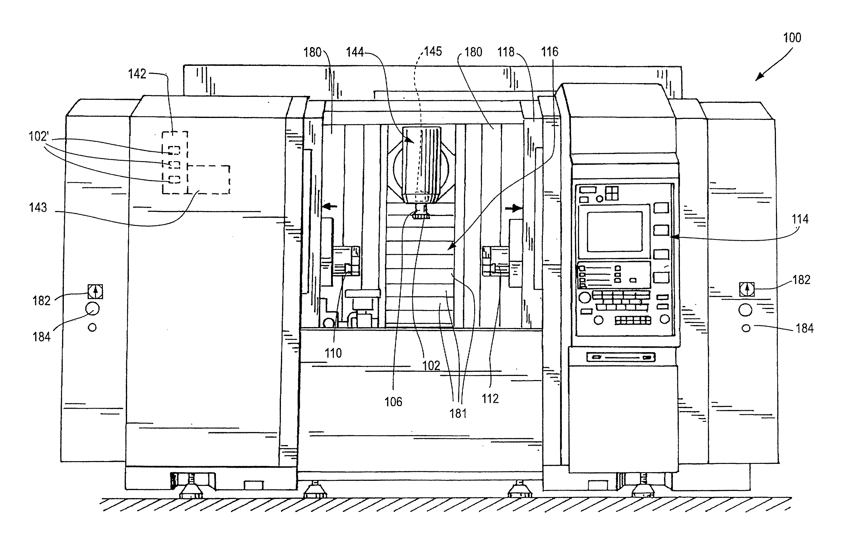
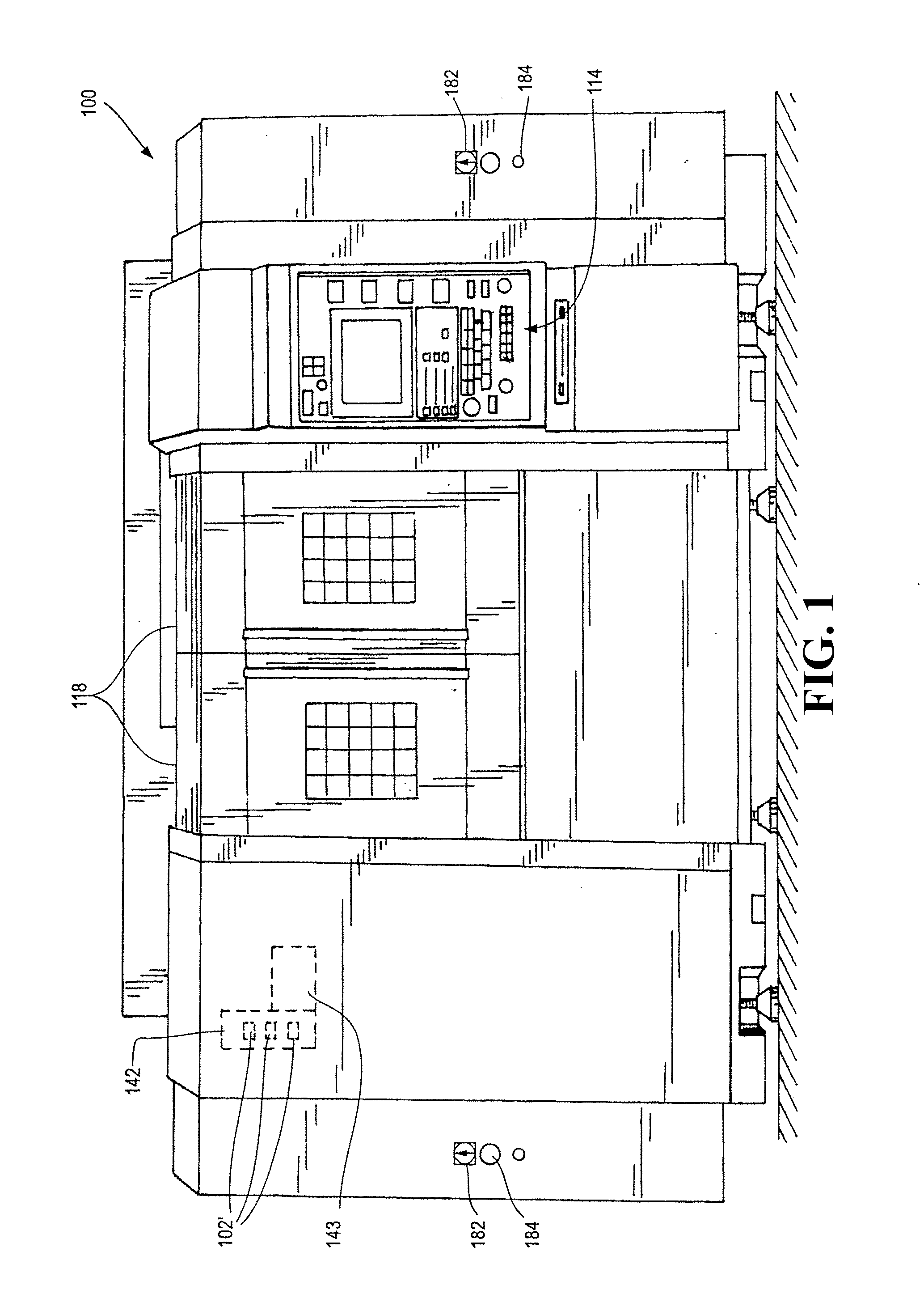
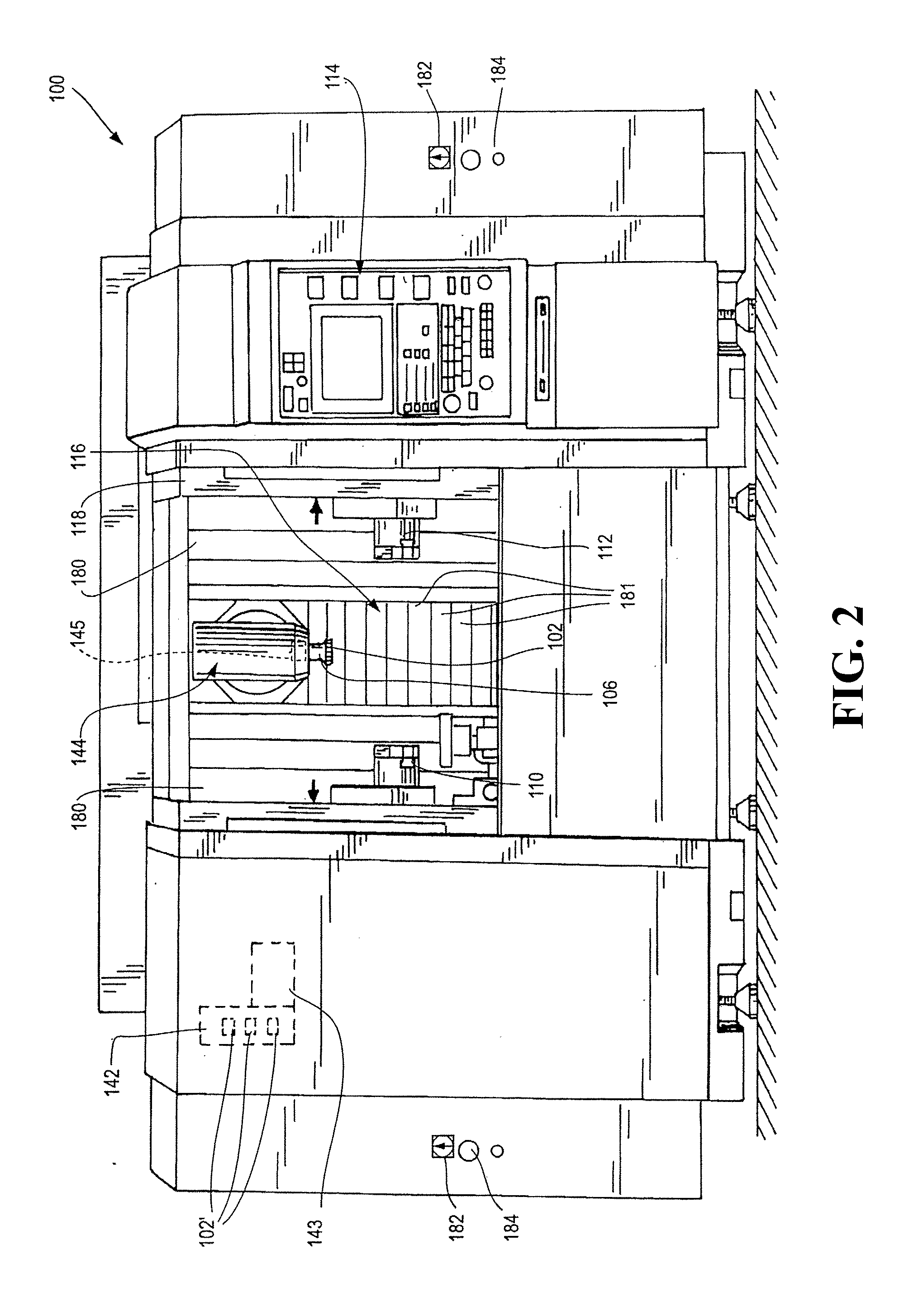
[0036]Any suitable apparatus may be employed in conjunction with the methods disclosed herein. In some embodiments, the methods are performed using a computer numerically controlled machine, illustrated generally in FIGS. 1-9. A computer numerically controlled machine is itself provided in other embodiments. The machine 100 illustrated in FIGS. 1-9 is an NT-series machine, versions of which are available from DMG / Mori Seiki USA, the assignee of the present application. Other machines, ...


PUM

PropertyMeasurementUnit
Lengthaaaaaaaaaa
Pressureaaaaaaaaaa
Diameteraaaaaaaaaa

Abstract

A method of grind hardening a workpiece is provided. The method may include securing the workpiece in a workpiece retainer and a grind tool in a tool retainer, rotating the grind tool in a first angular direction at a first angular speed, controlling the workpiece and tool retainers such that the grind tool engages the workpiece, and controlling the workpiece and tool retainers such that the grind tool is guided along a grinding track of the workpiece. The grind tool may engage and/or disengage the workpiece at portions of sacrificial material disposed thereon. Coolant and cleaning nozzles may be provided and controlled such that at least a portion of the coolant from the coolant nozzle is diverted to the cleaning nozzle in a manner which reduces heat dissipation, improves thermal efficiency of the grind hardening and reduces loading of the grind tool.

Description

BACKGROUND[0001]1. Technical Field[0002]The present disclosure generally relates to computed numerically controlled machine tools, and more particularly, to methods and apparatus for performing grind hardening processes using computer controlled machine tools.[0003]2. Description of the Related Art[0004]Computed Numerically Controlled (CNC) machine tools are generally known for forming metal and wooden parts. Such machine tools include lathes, milling machines, grinding machines, and other tool types. More recently, machining centers have been developed, which provide a single machine having multiple tool types and capable of performing multiple different machining processes. Machining centers may generally include one or more tool retainers, such as spindle retainers and turret retainers holding one or more tools, and a workpiece retainer, such as a pair of chucks. The workpiece retainer may be stationary or move (in translation and / or rotation) while a tool is brought into contact...

Claims


Application Information

Patent Timeline
IPC IPC(8): B24B51/00
CPCB24B51/00B24B5/02B24B55/02C21D7/00
Inventor NIEMEYER, NILSFOECKERER, TOBIASCHAPHALKAR, NITINHYATT, GREGORY A.
Owner DMG MORI SEIKI CO LTD
Why Eureka
Try Eureka