Active Alignment Using Continuous Motion Sweeps and Temporal Interpolation

a technology of active alignment and sweeps, applied in the direction of computer control, program control, instruments, etc., can solve the problems of inability to compensate for all potential, inability to align about the optical or z axis, and inability to uniformly align optical elements and lenses

Active Publication Date: 2013-10-17
AUTOMATION ENG
View PDF2 Cites 129 Cited by
  • Summary
  • Abstract
  • Description
  • Claims
  • Application Information

AI Technical Summary

Problems solved by technology

Consequently, the optical elements and lenses are often not uniform, from piece to piece.
Unfortunately, this method allows adjustment of only the distance between the optical elements and the sensor along the z axis (the optical axis).
Such an alignment methodology cannot compensate for all potential asymmetries in the optical elements or imperfect alignment of the optical elements within the barrel.
Note that alignment about the optical or z axis is generally not possible with the threaded barrel a

Method used


Image

  • Active Alignment Using Continuous Motion Sweeps and Temporal Interpolation
  • Active Alignment Using Continuous Motion Sweeps and Temporal Interpolation
  • Active Alignment Using Continuous Motion Sweeps and Temporal Interpolation

Examples


Embodiment Construction

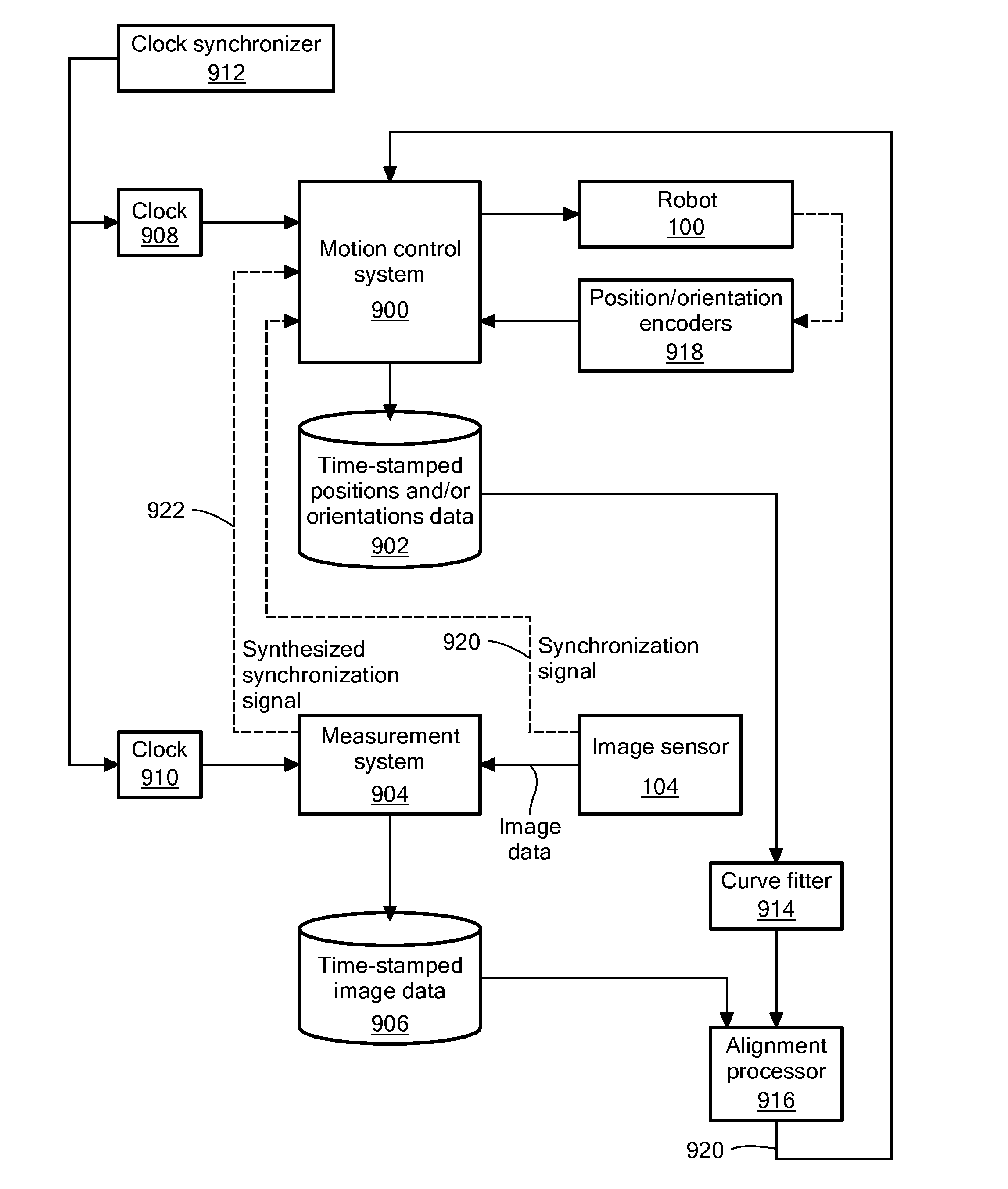
[0011]An embodiment of the present invention provides a computer-implemented method for actively aligning a first optical element to a second optical element. The method involves performing operations by a processor. A robot continuously scans the first optical element along a trajectory from a starting location to an ending location. While the robot continuously scans the first optical element from the starting location to the ending location, a plurality of time spaced-apart positions of the first optical element are stored. In addition, a plurality of time spaced-apart alignment data items is acquired. Each alignment data item of the plurality of time spaced-apart alignment data items results from an optical signal that passed through the first optical element and was received by the second optical element. Each alignment data item contains data indicative of a degree of optical alignment between the first optical element and the second optical element. A desired alignment positi...


PUM


Abstract

Methods and apparatus for actively aligning a first optical element, such as a lens, to a second optical element, such as an image sensor, use continuous scans, even absent a synchronization signal from one of the optical elements. During a scan, timed position information about the scanned optical element is collected, and then a relationship between position of the scanned optical element and time is estimated, such as by fitting a curve to a set of position-time pairs. This relationship can then be used to estimate locations of the scanned optical element at times when image data or other alignment quality-indicating data samples are acquired. From this alignment quality versus location data, an optimum alignment position can be determined, and the scanned optical element can then be positioned at the determined alignment position.

Description

CROSS REFERENCE TO RELATED APPLICATIONS[0001]This application claims the benefit of U.S. Provisional Patent Application No. 61 / 623,932, filed Apr. 13, 2012, titled “Active Alignment Using Continuous Motion Sweeps and Temporal Interpolation,” the entire contents of which are hereby incorporated by reference herein, for all purposes.TECHNICAL FIELD[0002]The present invention relates to automatic robotic alignment of optical components during manufacture or testing and, more particularly, to apparatus and methods that involve continuous motion sweeps of the optical components through potential alignment positions to optimize placement of the optical components.BACKGROUND ART[0003]Robots are used in many precision manufacturing processes. For example, robots are used to precisely align lenses before digital camera sensors, such as in the manufacture of cell phones and backup cameras for automobiles. In other examples, robots align ends of optical fibers before lasers or light sensors in...

Claims


Application Information

Patent Timeline
IPC IPC(8): B25J9/16
CPCB25J9/1697Y10S901/47G02B7/005G02B13/001G02B27/62
Inventor BY, ANDRE
Owner AUTOMATION ENG
Why Eureka
Try Eureka