Diversion of energy from regenerative braking

a technology of regenerative braking and energy, applied in the direction of automatic control system, battery/fuel cell control arrangement, instruments, etc., can solve the problems of increasing electricity costs for owners of such vehicles, electric vehicles often have a significantly reduced driving range when operating on electrical energy, and vehicles that cannot travel substantially less than recharge intervals

Inactive Publication Date: 2013-10-17
TOYOTA JIDOSHA KK
View PDF5 Cites 18 Cited by
  • Summary
  • Abstract
  • Description
  • Claims
  • Application Information

AI Technical Summary

Benefits of technology

[0009]A system or method for diverting energy as part of a regenerative braking system is described. In one embodiment, the present invention may provide a regenerative braking system for a vehicle including a generator coupled with the vehicle for generating energy. A battery is switchably coupled with the generator for receiving at least a portion of the energy from the generator. A first device is switchably coupled with the generator for receiving at least a portion of the energy from the generator and a second device is switchably coupled with the generator for receiving at least a portion of the energy from the generator. A processor is configured to control the switchable coupling of the battery, the first device and the second device with the generator based on a state of charge of the battery or an instantaneous temperature of air in an interior of the vehicle.
[0010]In another embodiment, the present invention may provide a system for diverting regenerative energy from a generator of an electric vehicle including a battery coupled with the generator through a first switch having a closed configuration and an open configuration, the battery configured to receive regenerative energy from the generator when the first switch is in the closed configuration. A heater is coupled with the generator through a second switch having a closed configuration and an open configuration, and the heater is configured to receive regenerative energy from the generator when the second switch is in the dosed configuration. An air conditioning unit is coupled with the generator through a third switch having a closed configuration and an open configuration, and the air conditioning unit is configured to receive regenerative energy from the generator when the third switch is in the closed configuration. A processor is coupled with the battery, the first switch, the second switch and the third switch. The processor is configured to control the first switch to the open configuration and the second switch or the third switch to the closed configuration if or when the battery has a state of charge above a predetermined threshold.
[0011]In still another embodiment, the present invention may provide a method of diverting energy in a regenerative braking system for an electric vehicle. The method comprises the steps of providing a battery, a heater and an air conditioning unit coupled with the electric vehicle, determining if or when the battery has a state of charge above a predetermined threshold, determining if or when a temperature for air in an interior of the electric vehicle is desired and alternatingly transmitting at least a portion of the energy to the heater and to the air conditioning unit for maintaining a substantially constant temperature for air in the interior of the electric vehicle if or when the state of charge of the battery is above the predetermined threshold.

Problems solved by technology

Unfortunately, due to battery limitations, electric vehicles often have a significantly reduced driving range when operating on electrical energy.
This results in vehicles that can only travel substantially lessened distances between recharges of the batteries.
In addition, the electricity costs for owners of such vehicles increases due to the additional power consumption from charging the vehicle's batteries.
Unfortunately, conventional regenerative braking systems have a number of disadvantages.
Typical regenerative braking systems have efficiency losses due to their operation in charging the batteries and subsequently discharging the batteries to power the desired electrical components of the vehicle, such as cabin temperature control systems.
However, when the batteries reach a fill state of charge, they stop accepting regenerative energy from the regenerative braking system and the energy is instead dissipated, for example as heat, and goes unutilized by the electric vehicle systems.
Since a lower ambient temperature reduces the maximum charge capability of the batteries, regenerative energy that might otherwise be utilized in warmer temperatures to charge the batteries to a full state of charge sees a decrease in efficiency when exposed to colder temperatures.
Not only is this non-utilization wasteful from an energy standpoint, but it also affects vehicle performance by altering the deceleration rate of the electric vehicle.
Thus, the driver will be distressed when the vehicle slows or brakes at different rates as it is allowed to coast to a stop.
Not only is such operational performance stressful to drivers who may not understand if some component of the vehicle has malfunctioned or been damaged, but also negatively impacts driver satisfaction and necessitates extraneous concentration when slowing due to the perceived unpredictability of the vehicle during engine braking.

Method used


Image

  • Diversion of energy from regenerative braking
  • Diversion of energy from regenerative braking
  • Diversion of energy from regenerative braking

Examples


Embodiment Construction

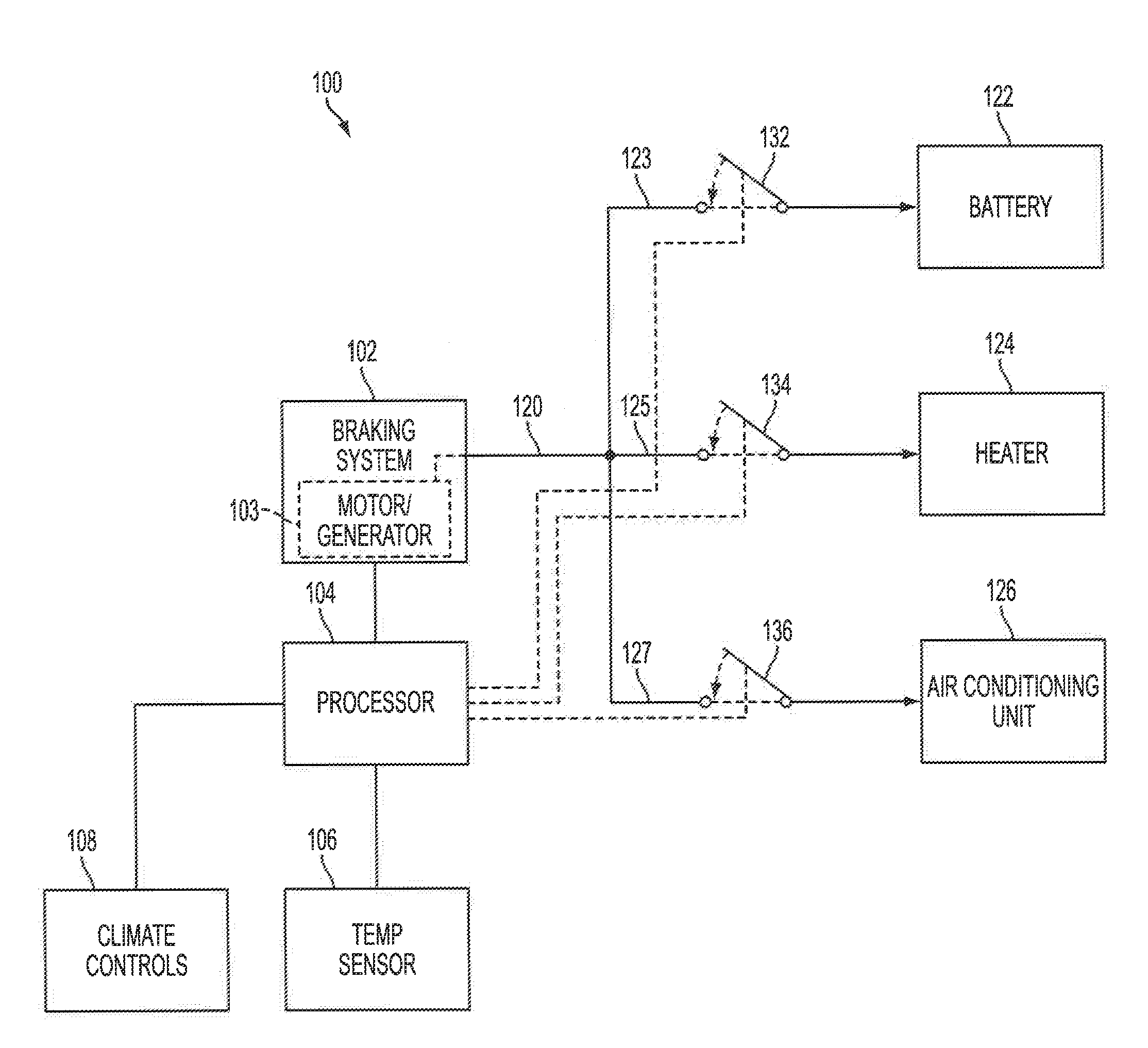
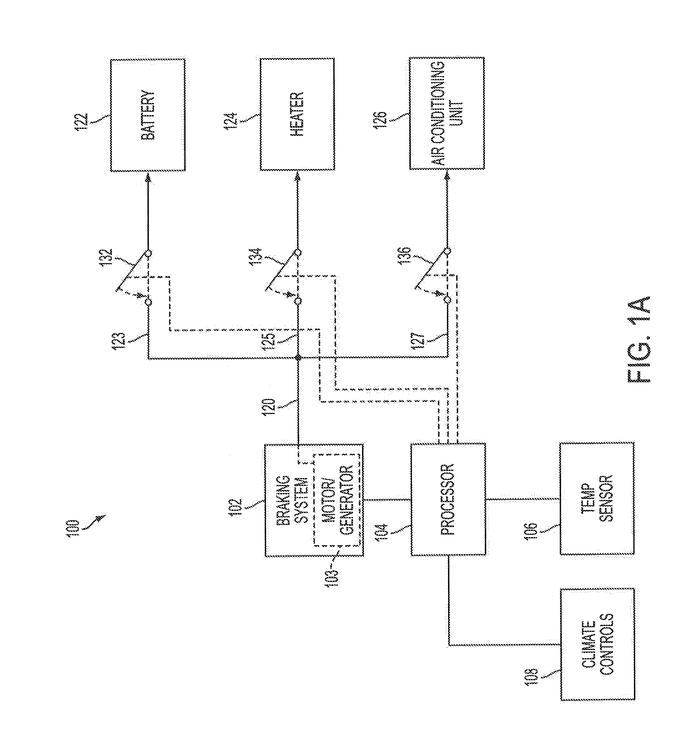
[0017]Referring to FIG. 1A, a block diagram is shown of a regenerative braking system 100 for a vehicle. The regenerative braking system 100 utilizes diversion of energy functionality in order to transmit or propagate energy to various components or devices of the regenerative braking system 100 of the vehicle, as discussed in greater detail herein. By diverting this regenerative energy to the vehicle components or devices, improved driveability results due to a maintained or substantially constant deceleration rate. The regenerative braking system 100 also allows such energy to be utilized by alternative components or devices if or when a specific component or device cannot currently use the provided energy. In addition, energy usage may also be more effectively utilized when directly transmitted to one or more components instead of first charging a battery and then discharging the battery for powering the one or more components.

[0018]The regenerative braking system 100 includes a ...


PUM


Abstract

A regenerative braking system for a vehicle utilizing diversion of energy for efficient use or maintaining consistent vehicle performance. The regenerative braking system includes a generator for producing regenerative energy during slowing and includes switches connected to a battery and a plurality of devices. A processor is connected with the battery and the switches for controlling the configuration of the switches based on a characteristic of the battery. If the battery has a state of charge exceeding a predetermined threshold, the processor controls the switches to route the regenerative energy to the other devices. The processor also controls the switches to provide regenerative energy to specific devices where it may most desirably be utilized. Heating and cooling units of the vehicle may be alternatively or simultaneously connected to receive the regenerative energy for providing consistent vehicle slowing performance when the battery state of charge exceeds the predetermined threshold.

Description

CROSS REFERENCE TO RELATED APPLICATIONS[0001]This application claims the benefit and priority of U.S. Provisional Application No. 61 / 624,024, filed on Apr. 13, 2012, the entire contents of which are hereby incorporated by reference.BACKGROUND[0002]1. Field[0003]The present invention relates generally to regenerative braking systems for electric vehicles and improvements thereof. More particularly, the present invention relates to a regenerative braking system utilizing diversion of energy for electric automobiles and improvements thereof.[0004]2. Description of the Related Art[0005]Electric vehicles are becoming increasingly popular among consumers concerned with saving costs or becoming more environmentally conscious. Electric vehicles help reduce the carbon footprint of an individual by lessening or eliminating the creation of toxic byproducts normally generated when operating a standard automobile that utilizes an internal combustion engine. By utilizing electrical power stored i...

Claims


Application Information

Patent Timeline
Patent Type & Authority Applications(United States)
IPC IPC(8): B60W10/196B60W30/188B60W10/30
CPCB60W10/196B60W10/30B60W30/1886B60W2600/00B60L1/003B60L1/02B60L3/0061B60L2240/36B60L2240/545B60W10/26B60W30/18127B60Y2300/92B60W20/14B60L58/12Y02T10/70Y10S903/903Y10S903/947B60L3/0046B60W2556/00
Inventor GREGG, CHRISTOPHERWARD, JUSTINKUSUMI, HIDETOSHI
Owner TOYOTA JIDOSHA KK
Why Eureka
Try Eureka