Pneumatic butterfly valve

Inactive Publication Date: 2013-10-24
HAMILTON SUNDSTRAND CORP
View PDF9 Cites 11 Cited by
  • Summary
  • Abstract
  • Description
  • Claims
  • Application Information

AI Technical Summary

Benefits of technology

The patent text describes a butterfly valve with a duct and a valve disc, and a pneumatic actuator that controls the rotation of the valve disc. A bleed conduit is used to pressurize the intermediate chamber to reduce the movement of the valve disc in the flow pathway. The technical effect of this patent is to provide an improved design for butterfly valves that reduces the likelihood of damage to the valve disc during operation.

Problems solved by technology

Unfortunately, balancing the two cavity pressures at the exact time the piston is in the selected position has proven to be difficult.
The piston often overshoots the selected position, thus resulting in valve instability.

Method used


Image

  • Pneumatic butterfly valve
  • Pneumatic butterfly valve
  • Pneumatic butterfly valve

Examples


Embodiment Construction

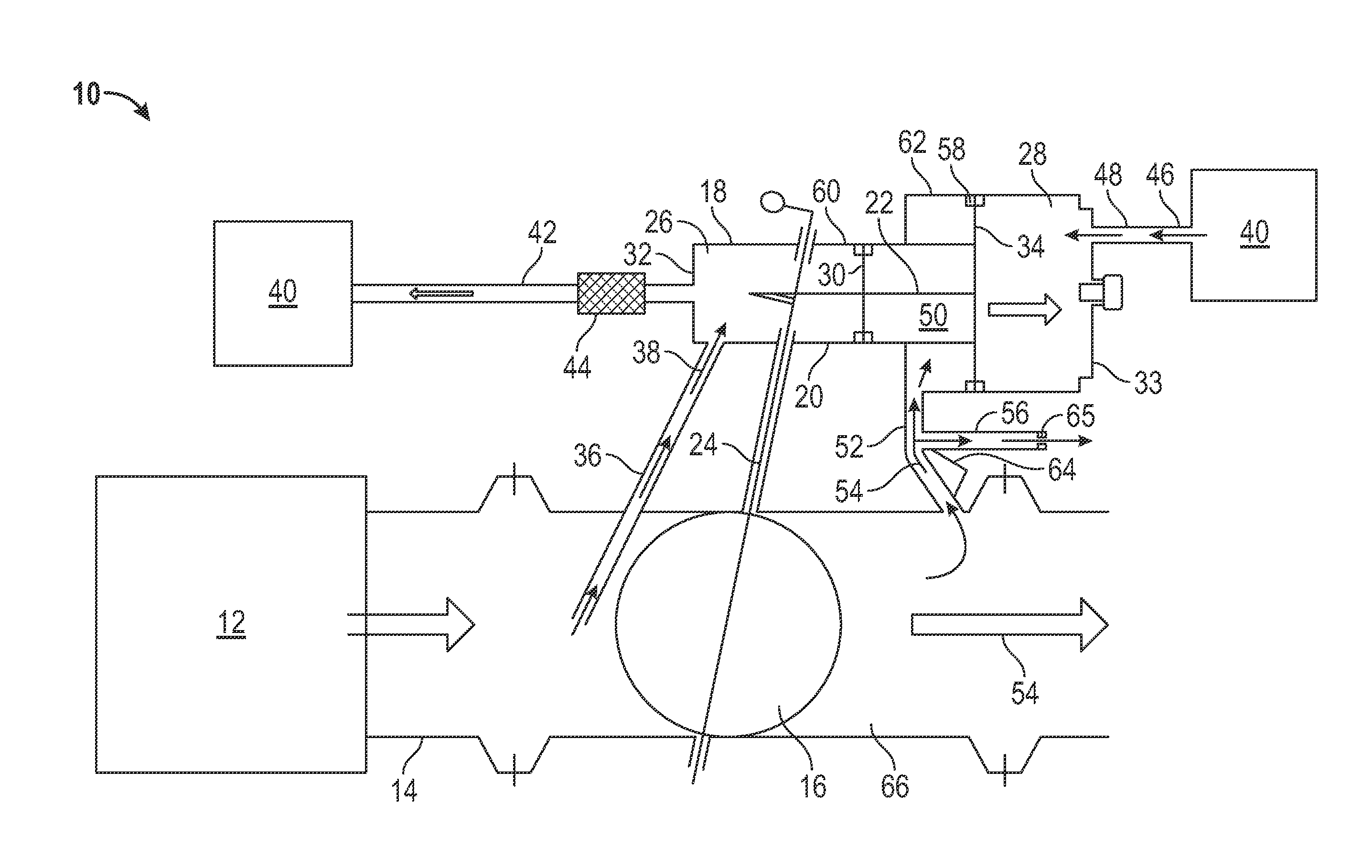
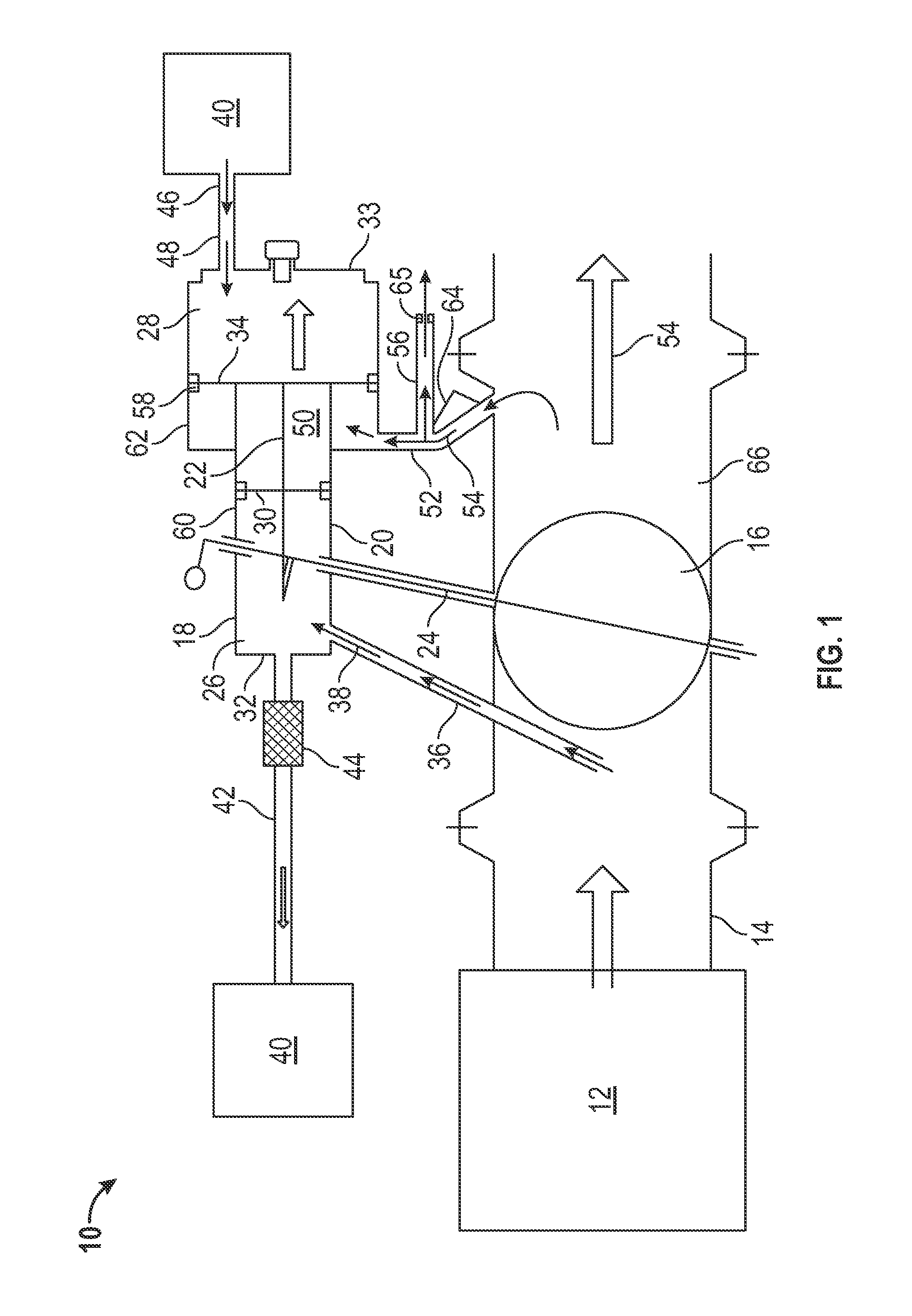
[0011]Shown in FIG. 1 is an embodiment of a pneumatically-operated butterfly valve 10, such as those utilized to regulate bleed airflow from, for example, a compressor 12. A bleed duct 14 extends from the compressor 12 to a valve duct 66, and a valve disc 16 is rotably positioned in the valve duct 66 such that rotation of the valve disc 16 decreases or increases flow allowable through the valve duct 66 and the bleed duct 14. The valve disc 16 is connected to a pneumatic actuator 18, which drives rotation of the valve disc 16. The actuator 18 includes a cylinder 20 with a piston 22 slidably positioned in the cylinder 20. The piston 22 is connected to the valve disc 16 via one or more linkages 24 to translate sliding motion of the piston 22 in the cylinder 20 into rotary motion of the valve disc 16.

[0012]Movement of the piston 22 in the cylinder 20 is determined by a difference in pressure between an upstream chamber 26 of upstream cylinder60 and a downstream chamber 28 of downstream ...


PUM


Abstract

A butterfly valve includes a duct defining a flow pathway and a valve disc rotably disposed in the flow pathway. A pneumatic actuator includes an intermediate chamber housing an actuator piston and is operably connected to the valve disc to drive rotation of the valve disc. A downstream bleed conduit extends from the flow pathway downstream of the valve disc to the intermediate chamber to pressurize the intermediate chamber thereby reducing a rate of movement of the valve disc in the flow pathway.

Description

BACKGROUND OF THE INVENTION[0001]The subject matter disclosed herein relates to valves. More specifically, the subject matter disclosed herein relates to control of butterfly valve positioning.[0002]A typical butterfly valve is controlled by a pneumatic actuator. The actuator includes a piston positioned in a cylinder. The piston is connected to a linkage that converts linear motion of the piston in the cylinder to rotary motion of the linkage. The linkage is, in turn connected to a butterfly disc located in a duct, or other flow structure. Rotation of the linkage rotates the butterfly disc in the duct, thus opening or closing the valve.[0003]In a typical cylinder of a butterfly valve, the cylinder has an upstream cavity connected to a pneumatic supply and a downstream cavity also connected to the pneumatic supply. A controller directs the pneumatic supply to increase or decrease the pressure in the downstream cavity to drive motion of the piston in the cylinder to either open or cl...

Claims


Application Information

Patent Timeline
IPC IPC(8): F16K1/22F16K31/00
CPCF16K31/122F16K1/221F04D27/0253F04D27/0215Y10T137/0318F05D2250/52
Inventor KAMP, JOSHSTRADINGER, JAYSCHRODER, BRUCE R.DOWD, PETER J.
Owner HAMILTON SUNDSTRAND CORP
Why Eureka
Try Eureka