Apparatus and Method for Producing Piston for Internal Combustion Engine

a technology of internal combustion engine and apparatus, which is applied in the direction of manufacturing tools, foundry moulding apparatus, foundry patterns, etc., can solve the problems of insufficient cost reduction and complicated production work

Active Publication Date: 2013-10-24
HITACHI ASTEMO LTD
View PDF0 Cites 8 Cited by
  • Summary
  • Abstract
  • Description
  • Claims
  • Application Information

AI Technical Summary

Benefits of technology

[0005]The present invention was made in consideration of the above-described problems in the technology of the conventional art. An object of the present invention is to provide an apparatus and method for producing a piston for an internal combustion engine which is capable of improving an operating efficiency in arrangement of a core in a die.
[0058]With this construction, it is possible to serve for good insertion and engagement of the moveable die and the guide die in the fixed die.

Problems solved by technology

As a result, the production work becomes complicated, and reduction in cost cannot be sufficiently attained.

Method used


Image

  • Apparatus and Method for Producing Piston for Internal Combustion Engine
  • Apparatus and Method for Producing Piston for Internal Combustion Engine
  • Apparatus and Method for Producing Piston for Internal Combustion Engine

Examples


second embodiment

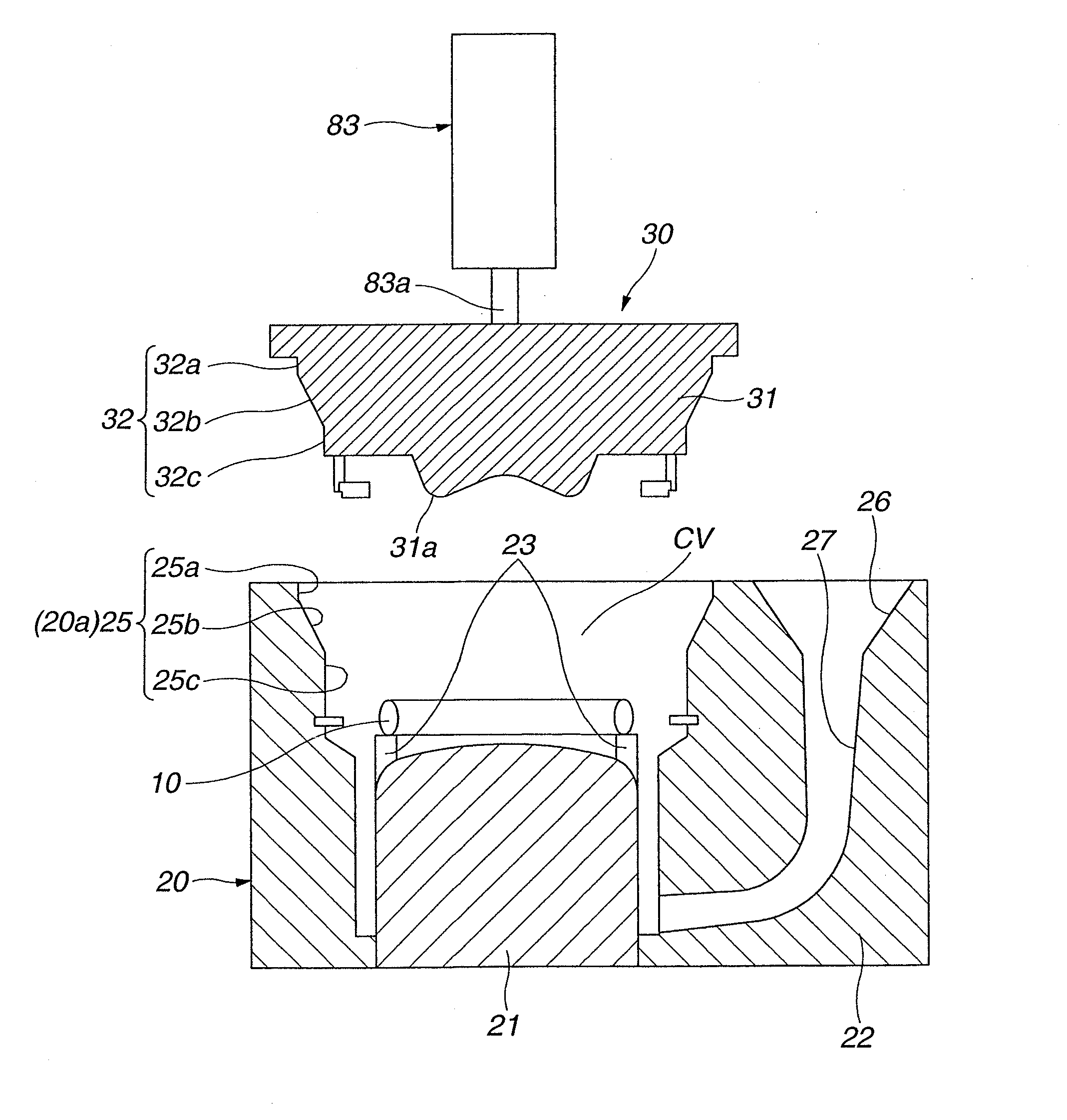
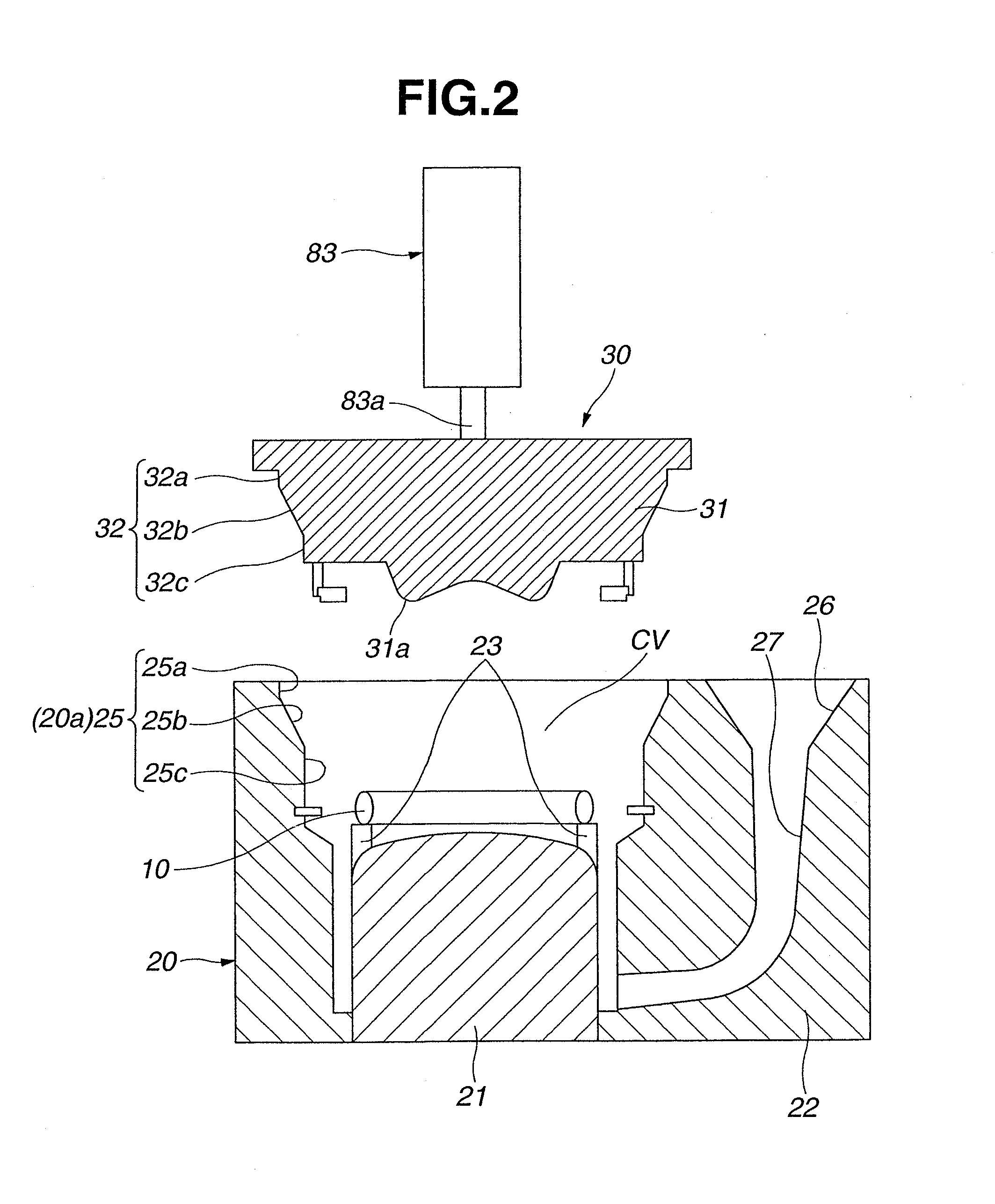
[0125]FIG. 14 shows an apparatus for producing a piston for an internal combustion engine according to the present invention. The second embodiment differs from the first embodiment in that a retaining configuration of core retaining mechanism 44 of jig 140 is modified. Like reference numerals denote like parts, and therefore, detailed explanations therefor are omitted.

[0126]In this embodiment, core retaining mechanism 44 of jig 140 includes pawls 72 slidable from the radially inner side of core 10 toward the radially outer side of core 10 so as to increase a distance between pawls 72 opposed to each other in the radial direction of core 10. Core 10 is retained by pressure contact between the inner peripheral portion of core 10 and pawls 72.

[0127]Specifically, in core retaining mechanism 44 of jig 140, generally cylindrical push member 74 is disposed on an outer peripheral side of base member 71, and chuck 73 including at least three pawls 72 is disposed on an inner peripheral side ...


PUM

PropertyMeasurementUnit
cylindrical shapeaaaaaaaaaa
air pressureaaaaaaaaaa
annular shapeaaaaaaaaaa

Abstract

An apparatus for producing a piston for an internal combustion engine by casting, the piston having a cooling channel therein, the apparatus including a fixed die with an upwardly opened cavity in which a core serving to form the cooling channel is to be disposed, a moveable die moveably disposed relative to the fixed die in a vertical direction and including a predetermined engaging portion, a guide die including an engaging portion engageable with the fixed die and having a same shape as that of the engaging portion of the moveable die, and a core retaining mechanism disposed in the guide die to retain the core in a predetermined position.

Description

BACKGROUND OF THE INVENTION[0001]The present invention relates to an apparatus and method for producing a piston for an internal combustion engine of a vehicle such as an automobile which has a cooling channel therein.[0002]A conventional piston for an internal combustion engine which is applied to an automobile is produced by metal mold casting as described in Japanese Patent No. 3548369.[0003]Specifically, a soluble core serving for forming a cooling channel is fixedly arranged in a die, and then, a molten metal is poured into the die to thereby form a workpiece for a piston. After that, the workpiece is withdrawn from the die, and the core is dissolved and removed by water and the like. Thus, the piston with the cooling channel is formed.SUMMARY OF THE INVENTION[0004]It is necessary to fulfill a predetermined positional relationship between the die and the core. For this reason, in the conventional method, the core is fixedly arranged in the die by a manual operation. As a result...

Claims


Application Information

Patent Timeline
Patent Type & Authority Applications(United States)
IPC IPC(8): B22D25/02B22C9/22
CPCB22D25/02B22C9/22F02B23/0696B22C9/105B22D17/24B22D18/02F02F3/22F02F2003/0007B22C9/10B22C9/108B22D17/02B22D19/0027
Inventor SASAKI, MASATOTAKAHASHI, NORIKAZU
Owner HITACHI ASTEMO LTD
Why Eureka
Try Eureka