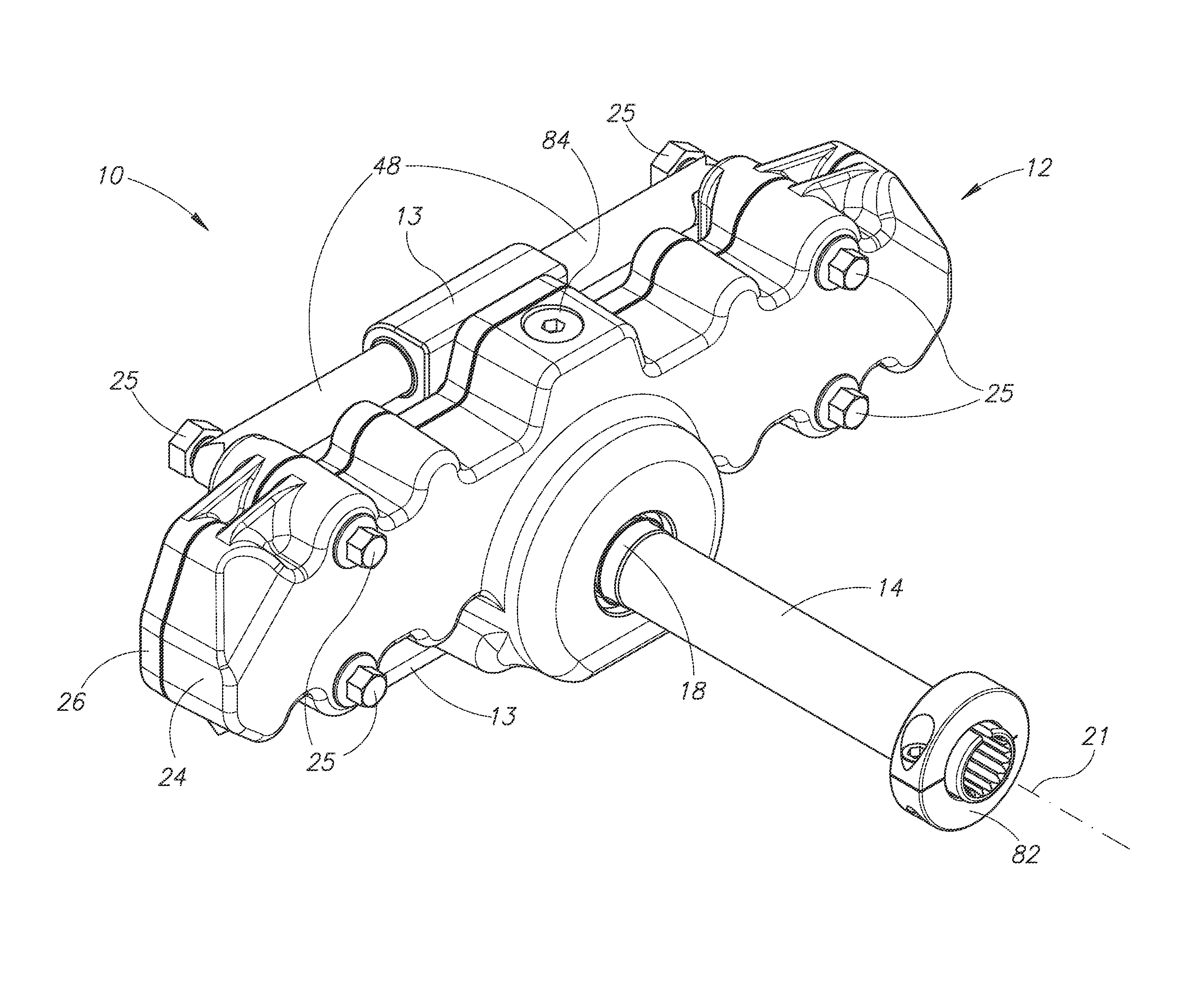
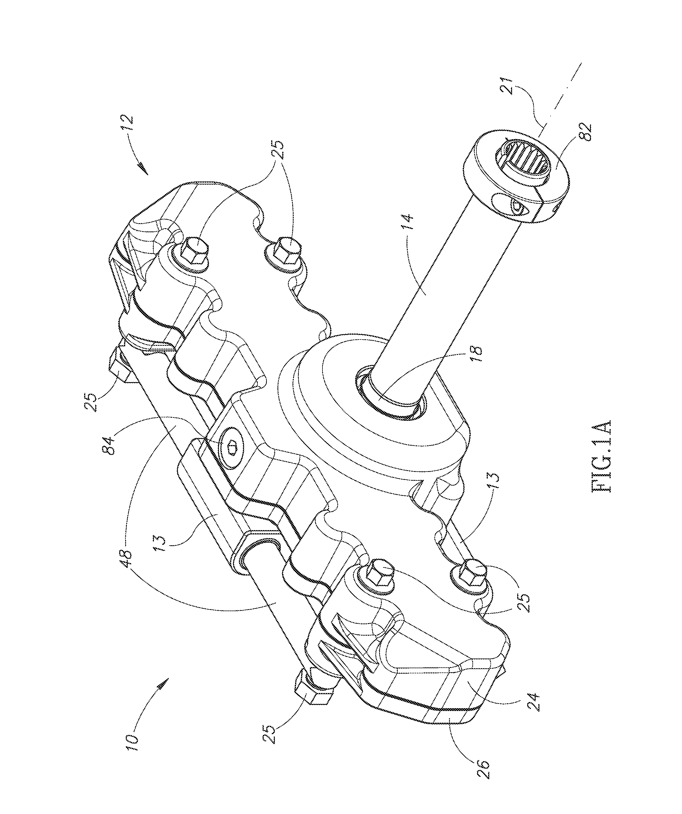
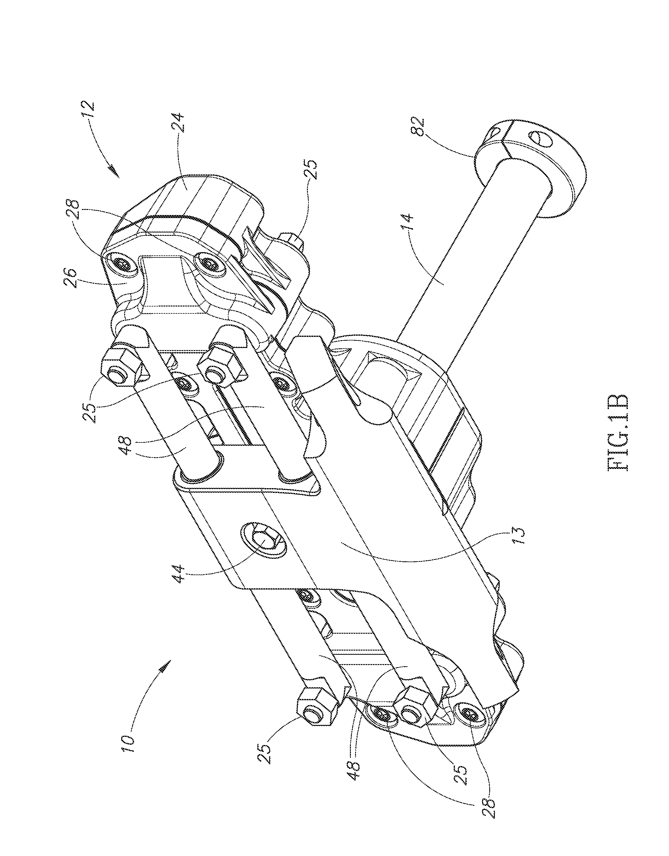
Compact steering mechanism
a steering mechanism and compact technology, applied in mechanical devices, transportation and packaging, cycles, etc., can solve problems such as inadvertent steering action, inconvenient coupling of tie rods to wheels, and fatigue or failure,
- Summary
- Abstract
- Description
- Claims
- Application Information
AI Technical Summary
Benefits of technology
Problems solved by technology
Method used
Image
Examples
second embodiment
[0067]FIG. 8D is another configuration of the second embodiment, whereby the output member is a single gear member 104 meshing with teeth 22 of rack 20. Gear member 104 is positioned to the right of pinion shaft 14 and between pinion 16 and the end of rack 20. Hole 110 is therefore coupled to both the left and right tie rod assemblies. Alternatively, gear member 104 may be positioned on either side of pinion shaft 16, or may be positioned in the middle portion of rack 20 to provide a center take-off point for steering the vehicle.
third embodiment
[0068]FIG. 9A is one configuration of the third embodiment described above. More specifically, the compact steering mechanism includes first gear 118 and a second gear 120 coupled to a rack guide 130 and rack mount 136, all being disposed within a steering housing (not shown). First gear 118, having a center, is coupled to pinion shaft 14 at an off-center portion of first gear 118 and above the center of first gear 118, when rack 20 is centered. Similarly, second gear 120, having a center, is coupled to a steering shaft 122 at an off-center portion of second gear 120 and above the center of the second gear 120, when rack 20 is centered (see FIG. 9E showing a side view of the gears coupled to the shaft above center). The teeth of first gear 118 mesh with the teeth of second gear 120. The center axis 124 of steering shaft 122 is parallel to center axis 21 of pinion shaft 14. Plates 132 may be coupled to the gears by fasteners 134 to secure first gear 118 to pinion shaft 14 and to secu...
first embodiment
[0073]FIG. 9D provides a front cutaway view of some components of the steering mechanism shown in FIGS. 9A and 9B. Steering housing 12 is provided as shown to allow flange 126 and holes 128 to extend beyond the perimeter of the steering housing for coupling to the pair of tie rods (similar to the steering pin of the first embodiment described above). As described above, pinion 16 is positioned within opening 140 of rack guide 130, wherein the teeth of pinion 16 mesh with the teeth of rack 20 at the middle portion of rack 20. As with previous embodiments, pinion 16 and flange 126 may be coupled along varying portions of rack 20 while maintaining the spirit of the invention.
[0074]FIG. 9E illustrates the relationship of the gears coupled off-center. It is shown that first gear 118 is coupled to pinion shaft 14 at an off-center position above center 119, and second gear 120 is also coupled to steering shaft 122 at the off-center position above center 119. It is further illustrated that ...
PUM
 Abstract
Description
Claims
Application Information
 - R&D
- Intellectual Property
- Life Sciences
- Materials
- Tech Scout
- Unparalleled Data Quality
- Higher Quality Content
- 60% Fewer Hallucinations
Browse by: Latest US Patents, China's latest patents, Technical Efficacy Thesaurus, Application Domain, Technology Topic, Popular Technical Reports.
© 2025 PatSnap. All rights reserved.Legal|Privacy policy|Modern Slavery Act Transparency Statement|Sitemap|About US| Contact US: help@patsnap.com


