Apparatus for pressure sensing

a technology of pressure sensing and apparatus, which is applied in the field of apparatus for pressure sensing, can solve the problems of difficult diagnosis, high cost of devices, and inconvenient use of diagnostic tools for patients, and achieve the effects of reducing pressure differences between adjacent internal spaces, increasing internal pressure, and increasing the movability of the movable wall portion

Inactive Publication Date: 2010-03-18
COMMONWEALTH SCI & IND RES ORG
View PDF9 Cites 4 Cited by
  • Summary
  • Abstract
  • Description
  • Claims
  • Application Information

AI Technical Summary

Benefits of technology

[0011]an internal space at each Bragg grating being in fluidal communication with an internal space at an adjacent Bragg grating whereby pressure differences between adjacent internal spaces are reduced.
[0013]As pressure differences between adjacent internal spaces are reduced, a local increase in internal pressure caused by a suitable movement of movable wall portion is reduced, which increases the movability of the movable wall portion and thereby the sensitivity of the apparatus.
[0018]The tube may have open end-portions or at least one end-portion of the tube may be closed. The apparatus typically is arranged for in-vivo pressure measurements and the tube typically has one open end that is arranged to be located outside a body during the in-vivo pressure measurements so that the internal spaces at the Bragg gratings are in fluidal communication with a space outside the body. The other end of the tube typically is closed. If the tube would have two closed ends, temperature fluctuations may cause pressure variations within the tube and such pressure variations could affect the strain of the at least one Bragg grating and thereby the accuracy of the in-vivo pressure measurements. The open end of the tube substantially avoids such pressure variations within the tube.
[0023]Further, the apparatus may comprise a portion comprising an X-ray opaque material which enables imaging of the position of the apparatus in the human body. For example, the apparatus may be arranged for positioning in the oesophagus of the human body for distributed pressure measurement in the oesophagus. With the above-described apparatus it is typically possible to measure a distributed pressure in the oesophagus in a manner such that a swallowing action or food travelling past a selected region does not significantly influence a pressure reading at another sensing region by an axial strain originating from the selected sensing region.
[0028]The apparatus may have a normal operating temperature and pressure range at which the Bragg gratings are distorted into respective internal spaces or alternatively may be distorted in an opposite direction. The apparatus may be arranged so that a temperature related change in a property of the moveable wall portions, which typically are positioned adjacent respective Bragg gratings, reduces the temperature related change in the optical response of the Bragg gratings. In this case the apparatus has the particular advantage that the moveable wall portion has a dual function, namely reducing the temperature related change in the optical period of the Bragg grating and causing a force on the Bragg grating in response to an external pressure change.

Problems solved by technology

It is difficult to diagnose this disease and diagnostic tools are often very uncomfortable for the patient.
Such devices typically are expensive and require a relatively large number of electrical wires to be contained in a catheter which consequently is of relatively large thickness.
The device is inserted through the nose of the patient and its relatively large diameter results in discomfort for the patient.

Method used


Image

  • Apparatus for pressure sensing
  • Apparatus for pressure sensing
  • Apparatus for pressure sensing

Examples


Embodiment Construction

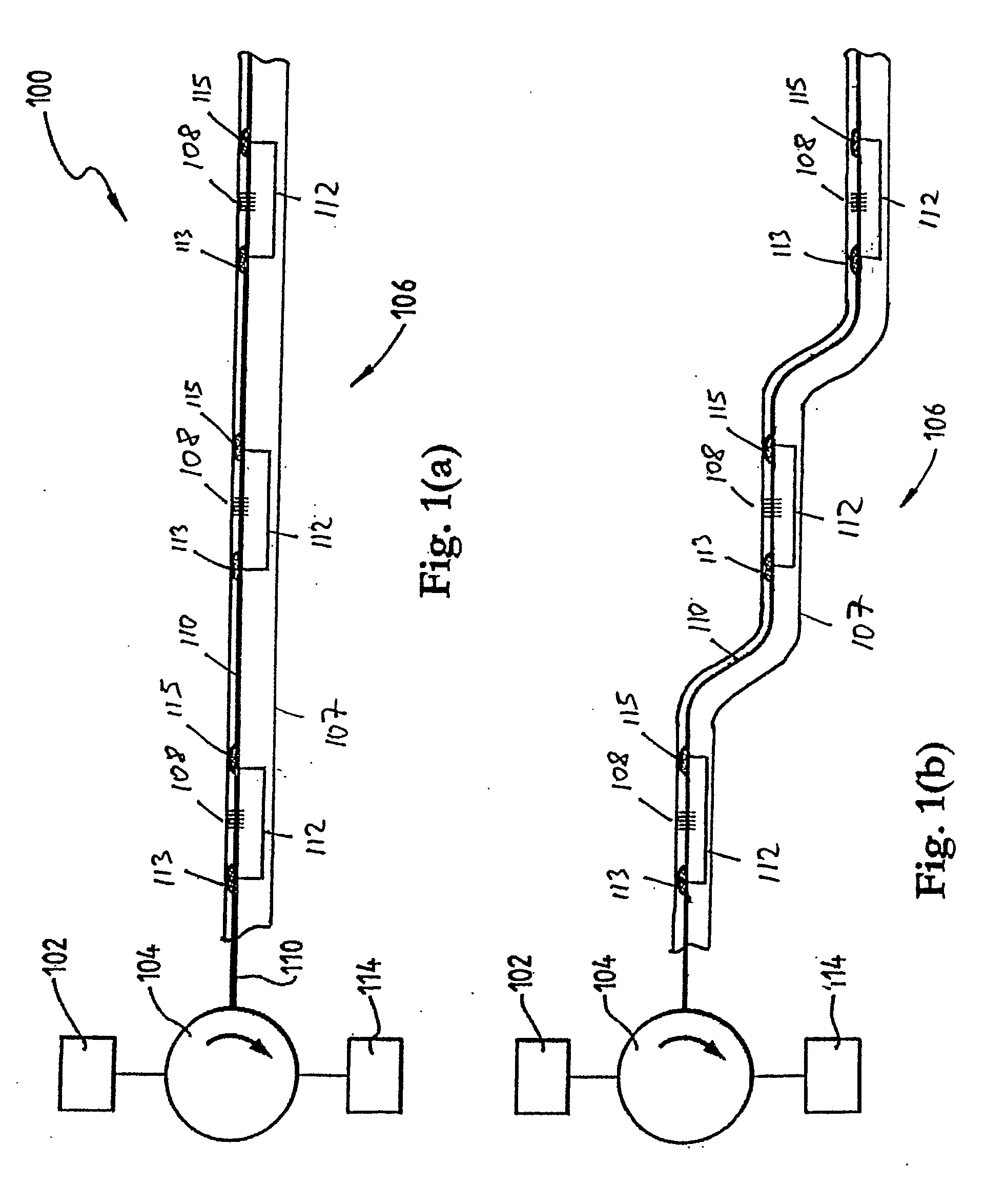
[0048]Referring initially to FIG. 1 (a), a system for distributed pressure sensing according to a specific embodiment of the present invention is now described. The system 100 comprises a light source 102 which in this embodiment is a broadband light source commonly referred to as a “white” light source even though the light that is emitted by the light source 102 may have any wavelength range.

[0049]The light is directed via optical circulator 104 to an apparatus for distributed pressure sensing 106. In a variation of this embodiment the circulator 104 may be replaced by an optical coupler, an optical splitter or an optical beam splitter.

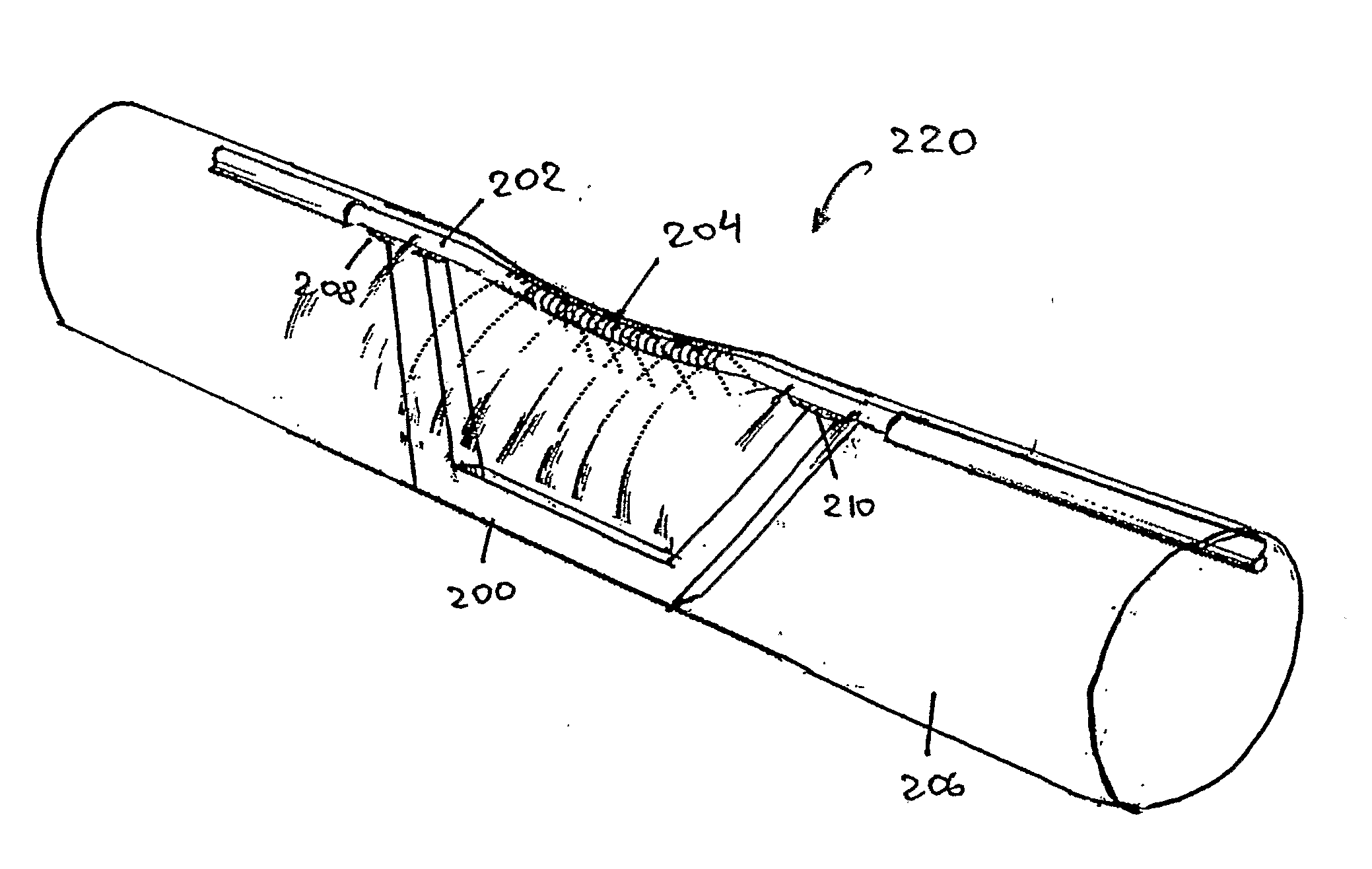
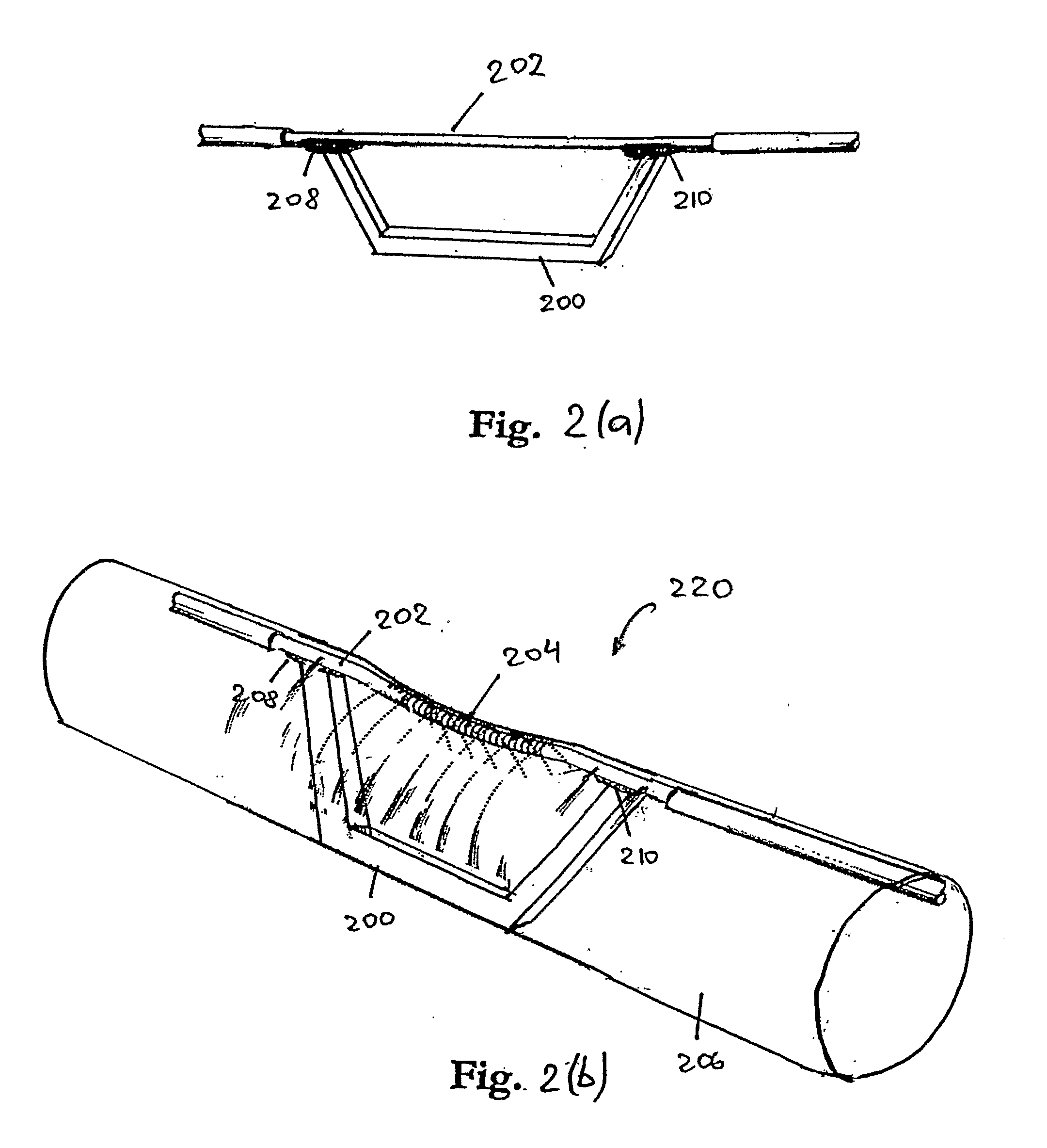
[0050]The apparatus 106 comprises a catheter 107 which is formed from a bio-compatible flexible material and arranged for insertion into a lumen of the human body. Further, the apparatus 106 typically comprises an X-ray opaque material, such as a metallic material, for locating the apparatus 106 in the human body.

[0051]The apparatus 106 comprises a ...


PUM

PropertyMeasurementUnit
operating temperatureaaaaaaaaaa
thicknessaaaaaaaaaa
pressureaaaaaaaaaa

Abstract

The present invention provides an apparatus for pressure sensing. The apparatus comprises a series of Bragg gratings and a light guide incorporating the series of Bragg gratings. The apparatus also comprises a plurality of moveable wall portions having opposite first and second sides. Each moveable wall portion is positioned so that a change in pressure at one of the sides relative to a pressure at the other side will move the moveable wall portion that is coupled to respective Bragg gratings so that the movement of one of the moveable wall portion causes a force on the respective Bragg grating resulting in a change in strain of the respective Bragg grating. An internal space at each Bragg grating is in fluidal communication with an internal space at an adjacent Bragg grating whereby pressure differences between adjacent internal spaces are reduced.

Description

FIELD OF THE INVENTION[0001]The present invention broadly relates to an apparatus for pressure sensing.BACKGROUND OF THE INVENTION[0002]The human body has many regions in which pressure differences cause matter to move. For example, the human heart pumps blood through the body. Muscles around the alimentary canal apply a pressure to the channel which moves food from the mouth into the stomach. Further, a pressure increase in a portion of the body may be caused by a chemical reaction such as the development of a gas in an enclosed body cavity.[0003]Monitoring pressures in the human body can provide important information about the function of the human body and can be used to detect disorders and diseases or can be used to control a recovery from a disease.[0004]For example, dysphagia, which is a disorder that causes difficulty in swallowing, typically affects infants and elderly people and is especially prevalent in post-stroke patients. It is difficult to diagnose this disease and d...

Claims


Application Information

Patent Timeline
Patent Type & Authority Applications(United States)
IPC IPC(8): A61B5/00G02B6/00G01L13/02
CPCA61B5/00G01D5/35316G01L11/025G01L1/246
Inventor ARKWRIGHT, JOHN WILLIAMDOE, SIMON NICHOLASJARVIS, BRIAN LAURENCEHARTMANN, ANDREAS
Owner COMMONWEALTH SCI & IND RES ORG
Why Eureka
Try Eureka