
Integrated direct drive motor and control

Active Publication Date: 2013-10-24
NIDEC MOTOR CORP
View PDF4 Cites 45 Cited by
  • Summary
  • Abstract
  • Description
  • Claims
  • Application Information

AI Technical Summary

Benefits of technology

The patent describes a motor design that saves money and improves signal quality by reducing the length of the wiring and lead wires needed between the control board and the motor. This design also eliminates the need for a dripshield housing to protect from water. Additionally, the integration of the control board and motor allows for packaging and sale as a single unit, rather than separate units. Overall, this patent offers a more efficient and cost-effective solution for motor and control board design.

Problems solved by technology

Such an approach is often inconvenient and expensive.
For instance, traditional outer rotor motors are limited to a specific mounting arrangement incorporated into the core fabrication process.
Furthermore, the metal core must be large enough to house the mounting openings, making the core heavy and expensive.
Even further, the increased number of components in the machine-motor system, including fasteners such as bolts or screws, slows the assembly process and increases the risk that a component necessary for assembly will be misplaced.
The extensive wiring required for such a configuration adds to the expense of the machine and also increases the potential for electromagnetic interference problems to arise.
The multiple connections required increase the risk that a faulty connection will hinder performance.
Finally, the high number of components and assembly steps increases the time required for assembly and, in turn, the total cost of the machine.

Method used


Image

  • Integrated direct drive motor and control
  • Integrated direct drive motor and control
  • Integrated direct drive motor and control

Examples


Embodiment Construction

[0020]The present invention is susceptible of embodiment in many different forms. While the drawings illustrate, and the specification describes, certain preferred embodiments of the invention, it is to be understood that such disclosure is by way of example only. There is no intent to limit the principles of the present invention to the particular disclosed embodiments.

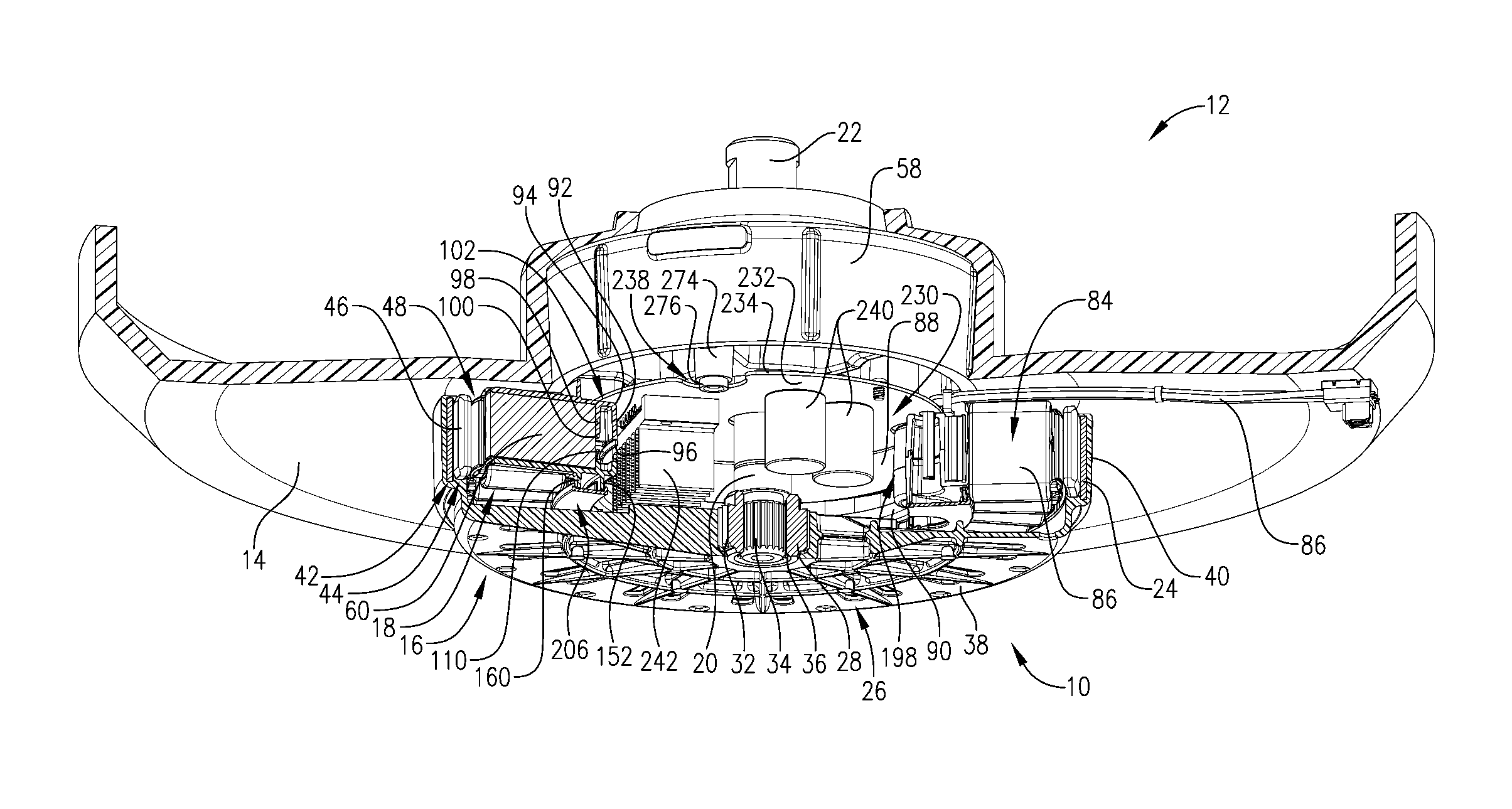
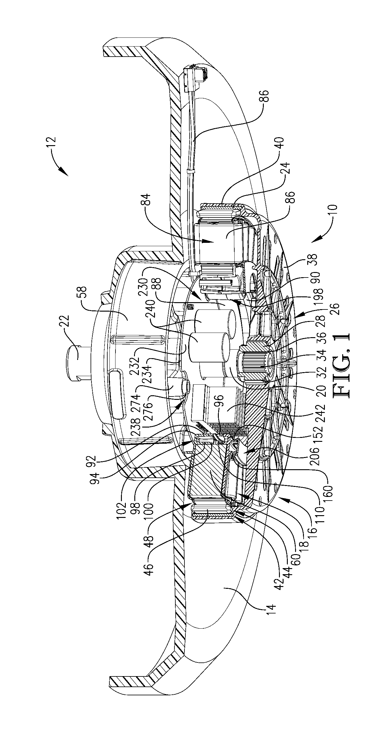
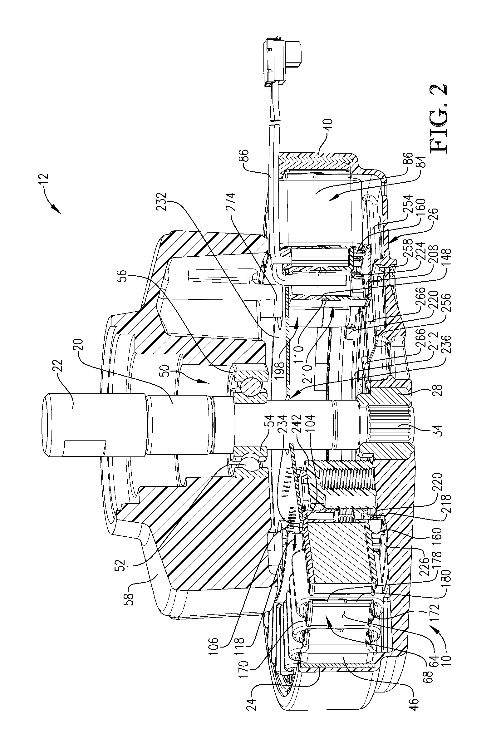
[0021]With initial reference to FIGS. 1 and 2, an electric motor 10 constructed in accordance with a preferred embodiment of the present invention is depicted for use in a machine 12. The particular machine depicted in FIGS. 1 and 2 is a washing mashing having a stationary tub 14 (not shown in FIG. 2) and a rotatable washer or agitator basket (not shown). However, a variety of machines, including but not limited to washing machines, fans, generators, and exercise equipment such as bicycles, are suitable for use with the present invention.

[0022]In a preferred embodiment, the motor 10 is an outer rotor motor that broad...


PUM


Abstract

An outer rotor motor is provided for use in a machine. The motor includes a rotor and a stator. A control board assembly configured to control at least one operational characteristic of the motor is mounted at least in part radially inside the stator.

Description

BACKGROUND OF THE INVENTION[0001]1. Field of the Invention[0002]The present invention relates generally to an electric motor for use in a machine. More specifically, the present invention concerns a direct drive motor having an integral control system.[0003]2. Discussion of the Prior Art[0004]Those of ordinary skill in the art will appreciate that electric motors are often used in home appliances such as dishwashers and washing machines. In a washing machine, for instance, an electric motor may be used to cause rotation of the washer basket to agitate the clothing contained therein. Although a variety of motor component arrangements may be used, one known embodiment of an electric motor includes a stator positioned at least in part radially inside a rotor. An electric motor having such a configuration is commonly referred to as an outer rotor motor or external rotor motor, although other names may be used. In the case of a washing machine having an electric motor of this sort, the r...

Claims


Application Information

Patent Timeline
IPC IPC(8): H02K5/22H02K5/18
CPCH02K1/187H02K1/32H02K3/522H02K5/08H02K5/1735H02K5/225H02K9/06H02K11/33H02K1/2791H02K3/345H02K5/04
Inventor PETERSON, GREGORY A.HILTON, DANIEL E.MAJOR, MICHAEL W.
Owner NIDEC MOTOR CORP
Learn More