
Ir hazard beacon

a technology of hazard beacons and beams, applied in the field of hazard beacons, can solve the problems of limited radiation spectrum and dangerous situations, and achieve the effect of reliable wind farms

Active Publication Date: 2013-10-24
SENVION GMBH
View PDF9 Cites 15 Cited by
  • Summary
  • Abstract
  • Description
  • Claims
  • Application Information

AI Technical Summary

Benefits of technology

The patent text describes a method to synchronize the flashing pulses of a visible LED and a NIR light source. This allows for the two sources to emit light at the same time. The light source can be integrated into a single component, making assembly easier. The technical effect of this synchronization is improved accuracy and efficiency in optical measurements and imaging.

Problems solved by technology

A drawback of LEDs, however, is that they have only a very limited radiation spectrum.
Since the spectral range of the LED flight navigation devices radiating only in the visual range does not correspond to the detection range of the night-vision devices, it is possible for wind energy plants to be overlooked during night flights, and dangerous situations can arise.

Method used


Image

  • Ir hazard beacon
  • Ir hazard beacon
  • Ir hazard beacon

Examples


Embodiment Construction

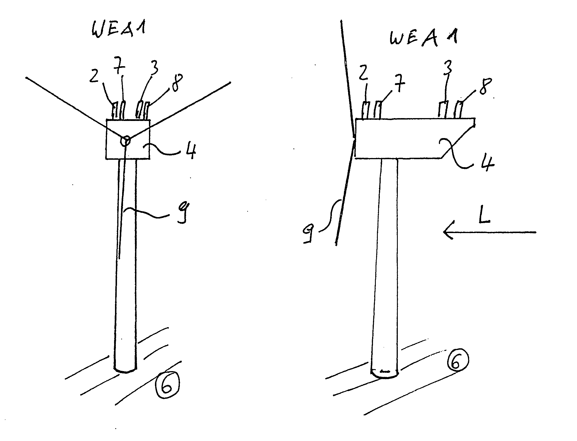
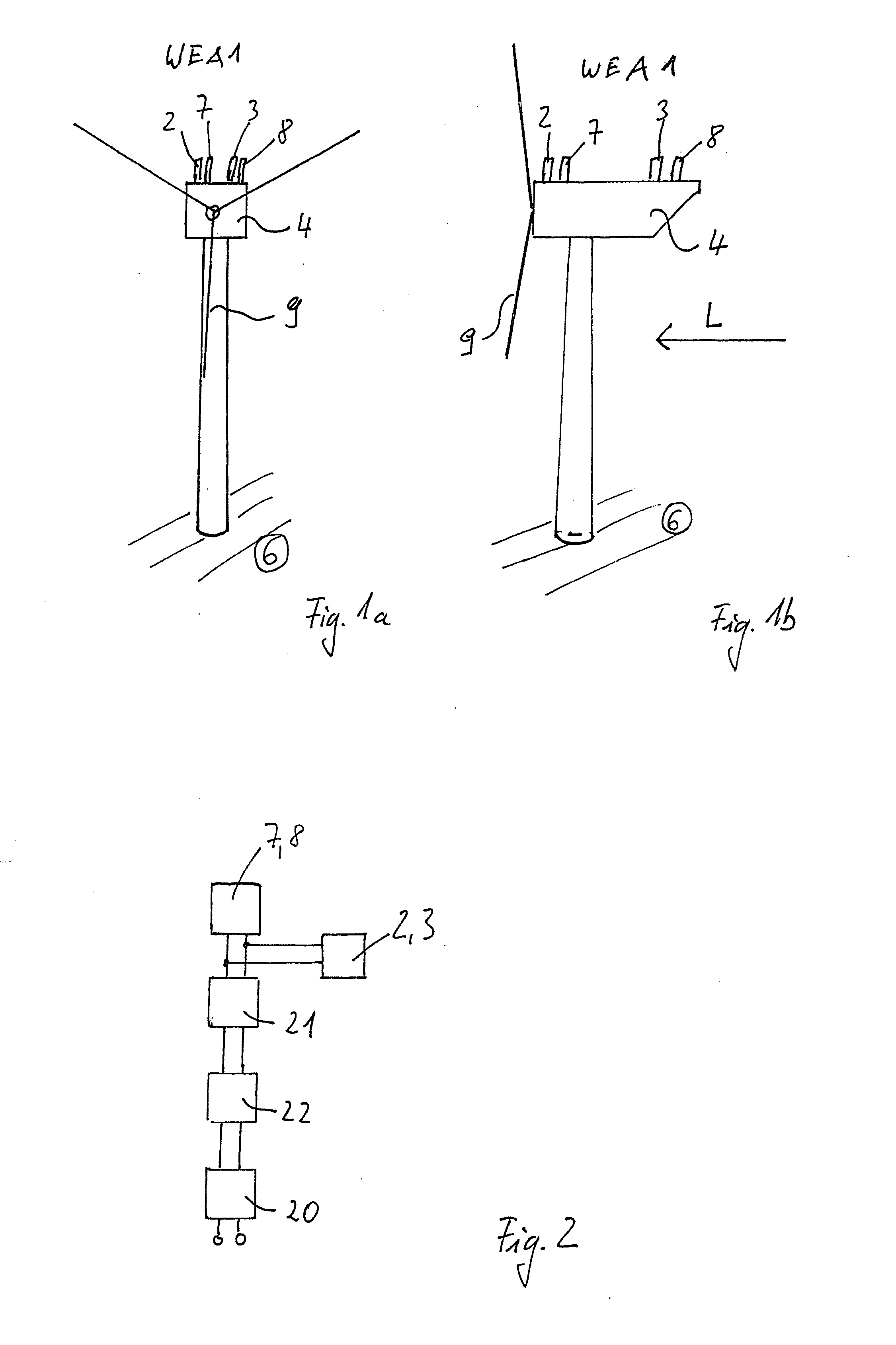
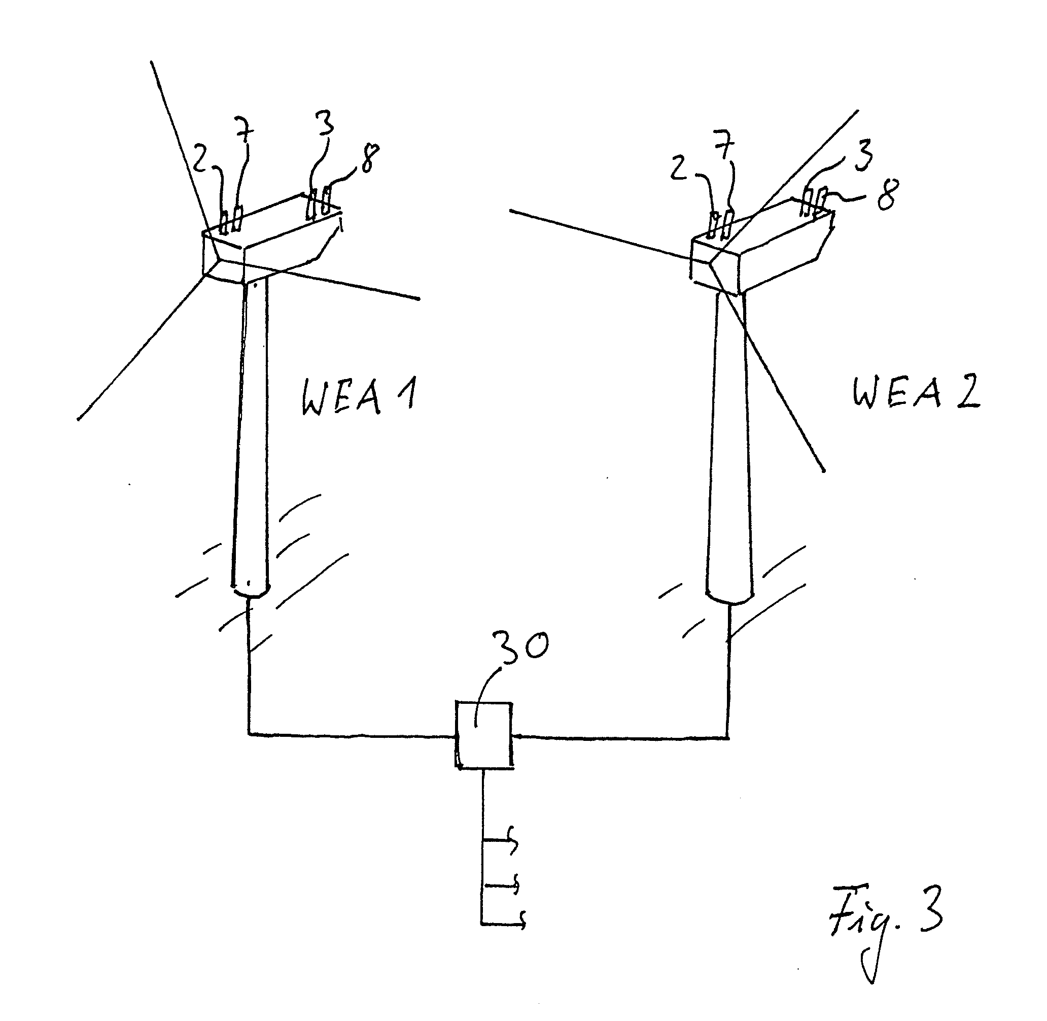
[0036]The wind energy plant WEA 1 according to the invention illustrated in FIG. 1a, FIG. 1b has, first of all, the at least two LED arrays 2, 3 which are used in a conventional manner and which are arranged at a distance from each other and obliquely offset on a roof of machine housing 4. An array is understood in this case as being a specified arrangement of a plurality of LEDs. It is also possible, however, for an individual LED to be provided in an LED array. In this case the relative arrangement of the two LED arrays 2, 3 is selected on the basis of safety regulations in such a way that in the front view as shown in FIG. 1 a from a point at the level of the machine housing 4 above sea level or the ground 6 to the machine housing 4 at least one of the two LED arrays 2, 3 will always be visible, despite the rotor blade 9 sweeping past or being stationary, in order to warn in a reliable manner a helicopter for example approaching at the level of the machine housing 4 of the wind e...


PUM


Abstract

The invention relates to a method for operating a wind turbine by switching on an aircraft warning light, the luminaries of which comprise LEDs, said LEDs radiating light with a maximum intensity in the range of visible light. At least one NIR LED is switched on when the aircraft warning light is switched on, said at least one NIR light source radiating light with a maximum intensity in the NIR range.

Description

CROSS REFERENCE TO RELATED PATENT APPLICATIONS[0001]This patent application is filed herewith for the U.S. National Stage under 35 U.S.C. §371 and claims priority to PCT application PCT / EP2011 / 004129, with an international filing date of Aug. 17, 2011. The contents of this application are incorporated in their entirety herein.STATEMENT REGARDING FEDERALLY-SPONSORED RESEARCH OR DEVELOPMENT[0002]Not applicable.TECHNICAL FIELD[0003]The invention relates to a method of operating a wind energy plant according to the preamble of claim 1 as well as to a wind energy plant for performing a method according to the preamble of claim 3. The invention also relates to a method of operating a wind farm as well as to a wind farm for performing the method.BACKGROUND OF THE INVENTION[0004]Depending upon the location and requirements, wind energy plants must be provided with a specified flight navigation device. In Germany, they must be marked for example by an obstruction light, a hazard beacon, a bl...

Claims


Application Information

Patent Timeline
Patent Type & Authority Applications(United States)
IPC IPC(8): G08G5/00
CPCG08G5/0047F03D80/10F21W2111/00F21W2111/06F21Y2113/13F21Y2115/10Y02E10/72
Inventor QUELL, PETERBOLZ, DETLEF
Owner SENVION GMBH
Learn More