
Display device

a display device and display technology, applied in the field of display devices, can solve problems such as luminance deterioration, and achieve the effect of suppressing crosstalk and avoiding luminance deterioration

Active Publication Date: 2013-10-24
SATURN LICENSING LLC
View PDF6 Cites 6 Cited by
  • Summary
  • Abstract
  • Description
  • Claims
  • Application Information

AI Technical Summary

Benefits of technology

[0009]In light of the foregoing, it is desirable to provide a novel and improved display device that is capable of displaying both a two-dimensional image and a three-dimensional image, and is further capable of suppressing the occurrence of crosstalk when displaying the three-dimensional image and also avoiding deterioration in luminance when displaying the two-dimensional image.
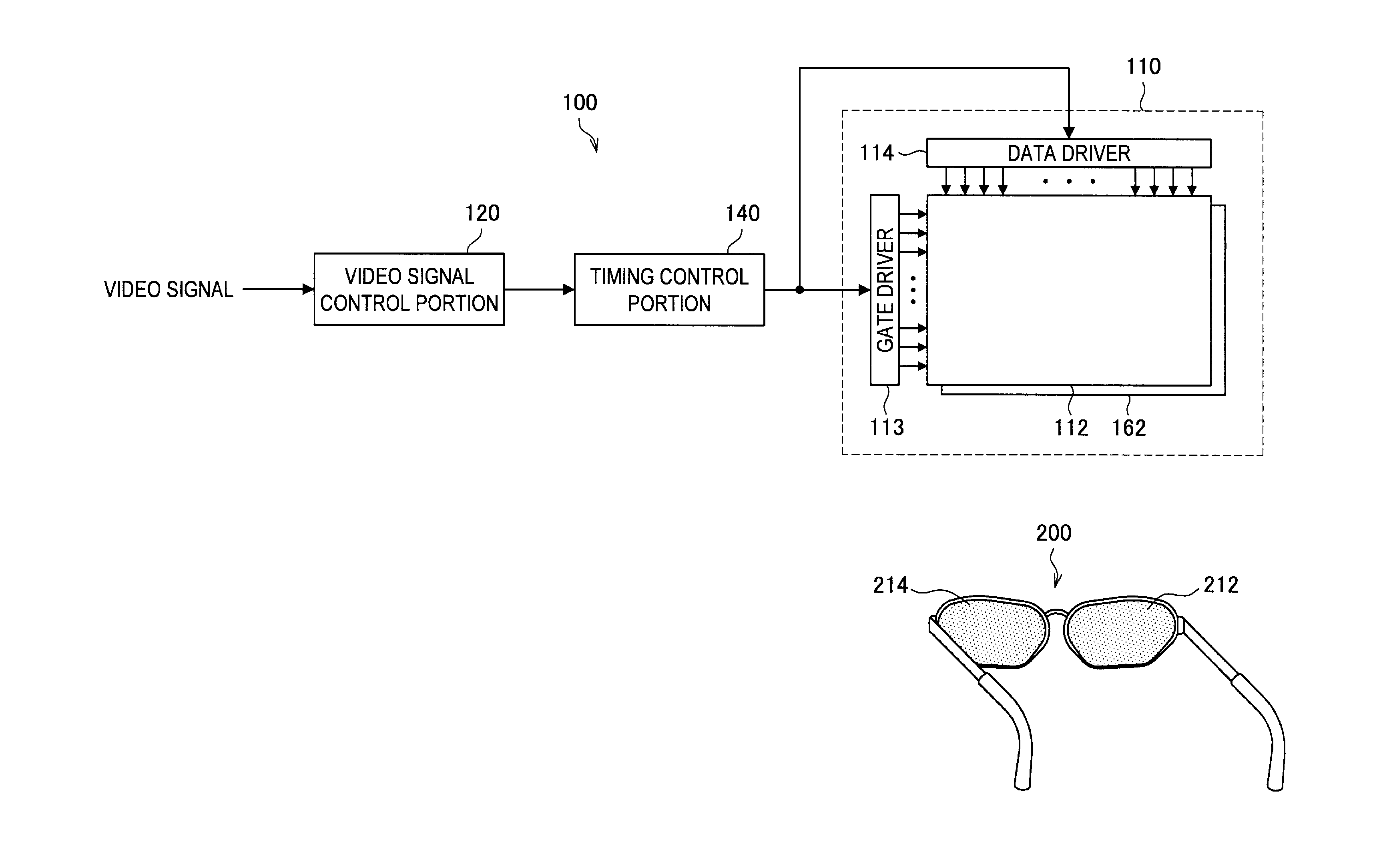
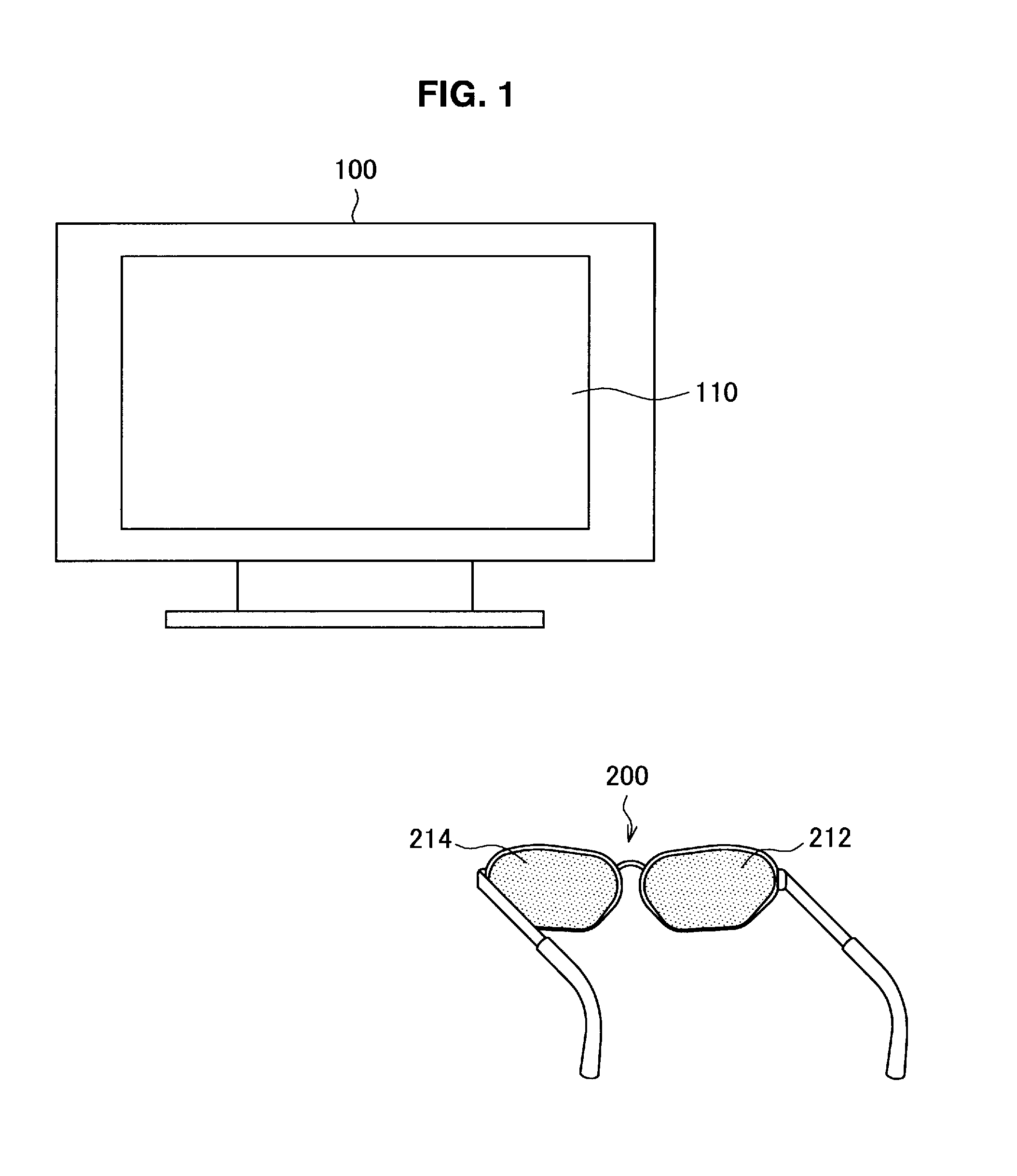
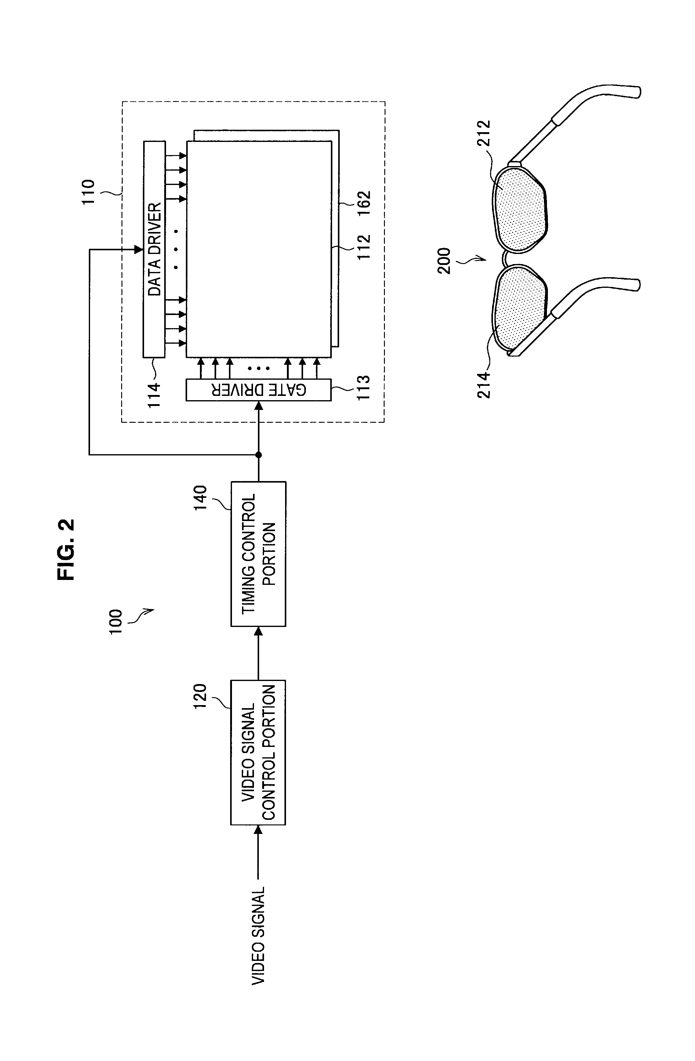
[0011]With the above structure, on the panel portion, the plurality of sub-pixels, which each have the discrete bus line, form each of the individual pixels, and the plurality of sub-pixels forming each of the individual pixels are sequentially arranged in the horizontal and the vertical directions. The panel portion displays one of the two-dimensional image and the three-dimensional image in accordance with a signal applied via the bus line. The filter portion, which is provided on the front surface of the panel portion, alternately changes, for each of the predetermined horizontal regions, the polarization state of the light that passes through the panel portion. Furthermore, the boundary of each of the horizontal regions of the filter portion is positioned within the range in which the first sub-pixel of each of the plurality of sub-pixels is provided. The first sub-pixel displays a different image when the two-dimensional image is displayed on the panel portion than when the three-dimensional image is displayed on the panel portion. As a result, deterioration in luminance can be avoided when the two-dimensional image is displayed, and crosstalk can also be suppressed when the three-dimensional image is displayed.
[0017]According to the present invention described above, it is possible to provide a novel and improved display device that can display both a two-dimensional image and a three-dimensional image. With the display device, as the boundary of each of the horizontal regions of the filter portion is positioned within the range in which the first sub-pixel of each of the plurality of sub-pixels is provided, crosstalk can be suppressed when displaying the three-dimensional image, and deterioration in luminance can also be avoided when displaying the two-dimensional image.

Problems solved by technology

However, when the black matrix is arranged on the boundary section in which the polarization state of the polarization control filter changes, when displaying a normal two-dimensional image on the screen, the black matrix causes deterioration in luminance.

Method used


Image

  • Display device
  • Display device
  • Display device

Examples


Embodiment Construction

)

[0026]Hereinafter, preferred embodiments of the present invention will be described in detail with reference to the appended drawings. Note that, in this specification and the appended drawings, structural elements that have substantially the same function and structure are denoted with the same reference numerals, and repeated explanation of these structural elements is omitted.

[0027]An exemplary embodiment of the present invention will be described in detail in the following order.

[0028]1. Example of known art

[0029]2. Embodiment of present invention

[0030]2-1. Structure of display device according to embodiment of present invention

[0031]2-2. Functional structure of display device according to embodiment of present invention

[0032]2-3. Structure of image display portion

[0033]2-4. Array of pixels on liquid crystal panel

[0034]3. Conclusion

1. EXAMPLE OF KNOWN ART

[0035]First, before giving a detailed description of the exemplary embodiment of the present invention, an image display meth...


PUM


Abstract

A display device includes: a panel portion, on which a plurality of sub-pixels with a discrete bus line form each individual pixel, the plurality of sub-pixels that form the individual pixel being sequentially arranged in a horizontal and a vertical direction, the panel portion displaying a two-dimensional image or a three-dimensional image by application of a signal via the bus line; and a filter portion, provided on a front surface of the panel portion, that alternately changes, for each of predetermined horizontal regions, a polarization state of light passing through the panel portion. A boundary of each of the horizontal regions of the filter portion is positioned within a range of a first sub-pixel of each of the plurality of sub-pixels. The first sub-pixel displays a different image when the two-dimensional image is displayed on the panel portion to when the three-dimensional image is displayed on the panel portion.

Description

CROSS-REFERENCE TO RELATED APPLICATION[0001]The present application is a continuation of U.S. patent application Ser. No. 12 / 660,180, filed Feb. 22, 2010, which claims priority from Japanese Patent Application No. JP 2009-049837 filed in the Japanese Patent Office on Mar. 3, 2009, the entire contents of which are incorporated herein by reference.BACKGROUND OF THE INVENTION[0002]1. Field of the Invention[0003]The present invention relates to a display device.[0004]2. Description of the Related Art[0005]Display devices exist in which an image displayed on a screen is perceived by a viewer as a stereoscopic three-dimensional image. In order to cause the viewer to perceive the image as a stereoscopic three-dimensional image, it is necessary to display the image on the screen using a different display method than a normal display method. One example of such a display method is a technique in which the viewer is caused to perceive an image as a stereoscopic image by changing a polarizatio...

Claims


Application Information

Patent Timeline
Patent Type & Authority Applications(United States)
IPC IPC(8): G09G5/02G09G3/30G09G3/36G02B30/25
CPCG09G5/02G09G3/3607G09G3/30H04N13/324H04N13/337H04N13/359
Inventor NAKAHATA, YUJI
Owner SATURN LICENSING LLC
Learn More