Terminal apparatus, feedback control method, base station, pairing control method, program, and wireless communication system

a technology of feedback control and terminal apparatus, which is applied in the field of terminal apparatus, feedback control method, base station, pairing control method, and wireless communication system, and can solve problems such as difficulty for the base station alone to know

Active Publication Date: 2013-10-24
SONY CORP
View PDF10 Cites 16 Cited by
  • Summary
  • Abstract
  • Description
  • Claims
  • Application Information

AI Technical Summary

Benefits of technology

[0026]According to a terminal apparatus, a feedback control method, a base station, a pairing control method, a program, and a wireless communication system in the present disclosure, as described above, pairing for MU-MIMO can flexibly be determined.

Problems solved by technology

However, it is difficult for the base station alone to know the channel to a mobile station and thus, feedback about the channel is given from the mobile station to the base station.

Method used


Image

  • Terminal apparatus, feedback control method, base station, pairing control method, program, and wireless communication system
  • Terminal apparatus, feedback control method, base station, pairing control method, program, and wireless communication system
  • Terminal apparatus, feedback control method, base station, pairing control method, program, and wireless communication system

Examples


first embodiment

2: First Embodiment

[2-1. System Overview]

[0058](1) System Configuration Example

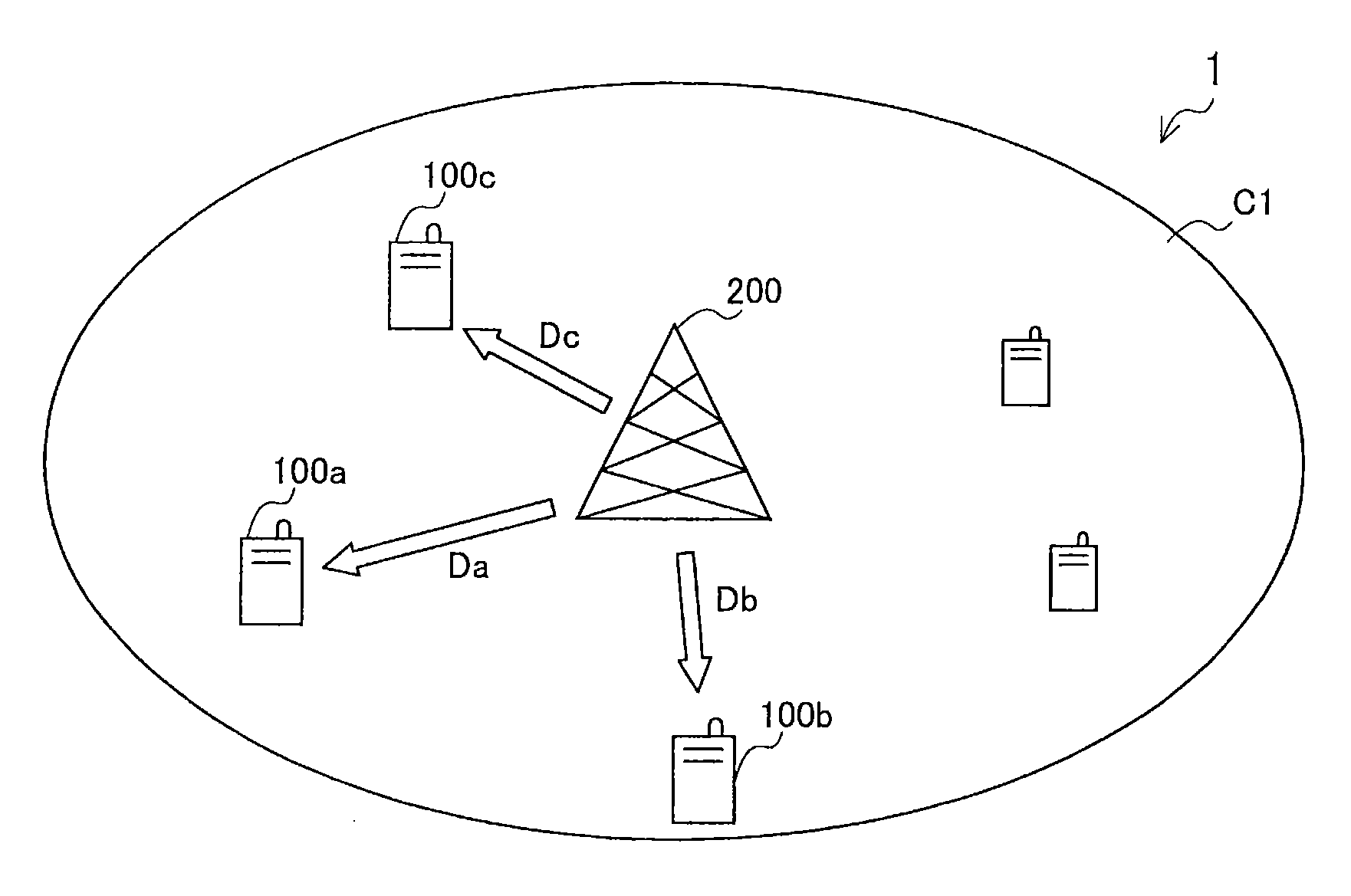
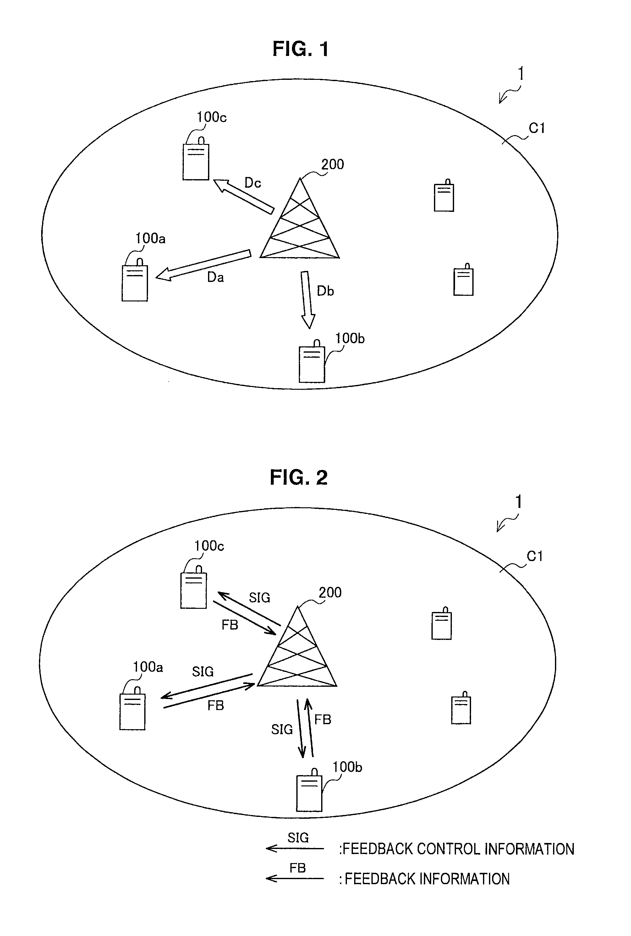
[0059]FIG. 1 is an explanatory view showing an overview of a cellular communication system 1 according to the first embodiment. Referring to FIG. 1, the cellular communication system 1 includes a plurality of mobile stations 100a to 100c and a base station 200. When there is no need to distinguish the plurality of mobile stations 100a to 100c in the description below, such mobile stations will generically be called a mobile station 100 by omitting the alphabet at the end of the code. This also applies to other elements.

[0060]The mobile station 100 is typically a terminal apparatus called UE (User Equipment). The mobile station 100 receives a radio signal transmitted from the base station 200 on a down-link channel with the base station 200 and transmits a radio signal to the base station 200 on an up-link channel with the base station 200. The mobile station 100 may also operate as a relay node relaying a...

second embodiment

3. Second Embodiment

[3-1. System Overview]

[0136]In the second embodiment described below, feedback in situations in which, in addition to MU-MIMO, CoMP is used is focused on.

[0137](1) System Configuration Example

[0138]FIG. 10 is an explanatory view showing an overview of a cellular communication system 2 according to the second embodiment. Referring to FIG. 10, the cellular communication system 2 includes a plurality of base stations 400a to 400c and a plurality of mobile stations 300a to 300f. The base station 400a is a serving base station of the mobile stations 300a to 300c. The base station 400b is a serving base station of the mobile stations 300e and 300f.

[0139]The mobile station 300a is positioned in a region near cell edges where a cell C2 of the base station 400a and a cell C3 of the base station 400b overlap and can receive signals from the two base stations 400a, 400b. Therefore, characteristics of the mobile station 300a can be improved by utilizing Joint Processing of ...


PUM


Abstract

Provided is a terminal apparatus including an estimation unit that estimates a channel to a base station by using a reference signal transmitted from the base station, a selection unit that selects a transmission weight desirable for second down-link transmission from the base station to another terminal apparatus spatially multiplexed with first down-link transmission on the channel from a plurality of transmission weight candidates in accordance with an estimation result by the estimation unit, and a feedback controller that controls feedback of the transmission weight selected by the selection unit to the base station.

Description

TECHNICAL FIELD[0001]The present disclosure relates to a terminal apparatus, a feedback control method, a base station, a pairing control method, a program, and a wireless communication system.BACKGROUND ART[0002]In the standardization of cellular communication technology of the fourth generation (4G) including LTE-A (Long Term Evolution-Advanced), MU-MIMO (Multiple User-Multiple Input Multiple Output) as further development of SU-MIMO (Single User-Multiple Input Multiple Output) is receiving attention. MU-MIMO is a technology enabling communication of a plurality of users in the same band simultaneously by spatial multiplexing and is expected to significantly improve communication throughput (see, for example, Non-Patent Literature 1 below).[0003]SU-MIMO is used in LTE (Long Term Evolution), which is also called the cellular communication technology of the 3.9-th generation. In SU-MIMO, a base station selects a transmission weight to be used for pre-coding of down-link transmission...

Claims


Application Information

Patent Timeline
Patent Type & Authority Applications(United States)
IPC IPC(8): H04W72/04
CPCH04W72/0406H04B7/024H04B7/0452H04B7/0634H04B17/318H04B17/373H04W72/20
Inventor TAKANO, HIROAKI
Owner SONY CORP
Why Eureka
Try Eureka