Cutting device and image forming system

a cutting device and image forming technology, applied in the direction of printing, metal working apparatus, sheet binding, etc., can solve the problems of large cutting device size, high cost, etc., and achieve the effect of simple mechanism and excellent cutting surfa

Inactive Publication Date: 2013-10-24
KONICA MINOLTA INC
View PDF4 Cites 3 Cited by
  • Summary
  • Abstract
  • Description
  • Claims
  • Application Information

AI Technical Summary

Benefits of technology

[0010]The present invention is made in view of the circumstances, and objects of the present invention include providing a cutting device and an image forming system each of which can obtain an excellent cut surface including the spine side thereof with a simple mechanism.

Problems solved by technology

For these reasons and the like, it is unavoidable that the cutting device has a large and / or complicated mechanism.
However, the conventional cutting device disclosed in Japanese Patent Application Laid-Open Publication No. 2004-66347 or Japanese Patent Application Laid-Open Publication No. 2011-25368 requires a complicated mechanism to change the direction of the inclination of the blade, and hence the cost is high.
In addition, the conventional cutting device requires a space for the mechanism, and hence it is unavoidable that the cutting device is large.
Also, the conventional cutting device requires time for a step to change the direction of the inclination of the blade, and hence its productivity is low.

Method used


Image

  • Cutting device and image forming system
  • Cutting device and image forming system
  • Cutting device and image forming system

Examples


Embodiment Construction

[0044]In the following, an embodiment of the present invention is described with reference to the drawings. The embodiment includes various technically-preferred limitations to realize the present invention. However, the scope of the present invention is not limited to the embodiment or the drawings.

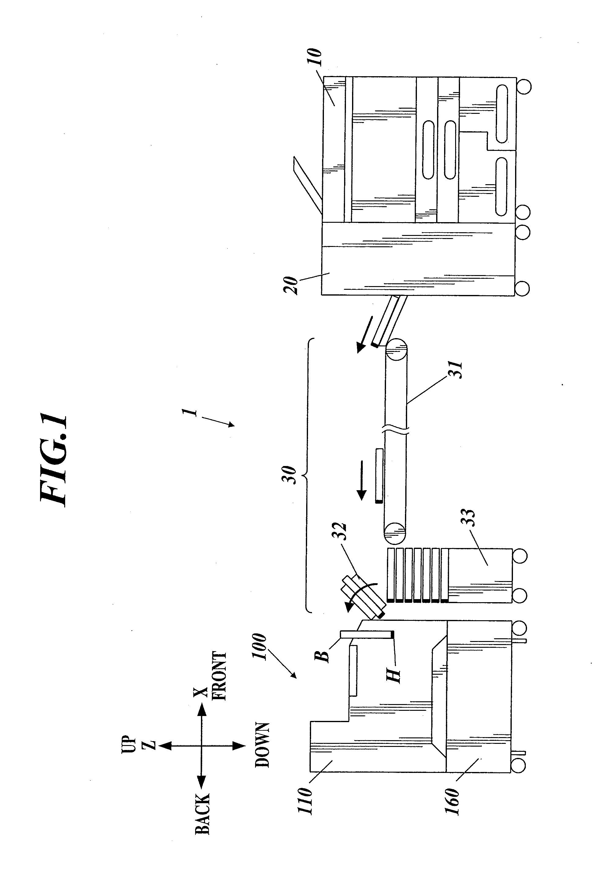
[0045]FIG. 1 shows main components of an image forming system 1 in accordance with an embodiment of the present invention.

[0046]The image forming system 1 includes an image forming device 10, a paper processing device 20, a carrier device 30 and a cutting device 100.

[0047]The image forming device 10 forms images on sheets of paper.

[0048]More specifically, the image forming device 10 includes a carrier unit, a developer unit, a primary transfer unit, a secondary transfer unit, a fixation unit and an ejection unit so as to form images on sheets of paper. The carrier unit takes out sheets of paper stored in a paper tray as a recording medium and carries the paper. The developer unit develop...


PUM


Abstract

A cutting device includes a cutting unit and a pre-processing unit. The cutting unit performs fore-edge cutting processing and top-edge/tail-edge cutting processing in a state in which a blade inclines toward a paper surface of a booklet. The fore-edge cutting processing is to cut off a first edge part of the booklet parallel to a spine of the booklet. The top-edge/tail-edge cutting processing is to cut off a second edge part of the booklet perpendicular to the spine. Of the top-edge/tail-edge cutting processing, in first top-edge/tail-edge cutting processing in which the blade cuts the booklet from a side opposite to the spine, before the blade abuts the spine, the pre-processing unit makes a cut at a point of the spine along a cutting direction in which the blade cuts the spine, the point where the blade abuts the spine.

Description

CROSS REFERENCE TO RELATED APPLICATIONS[0001]The present invention claims priority under 35 U.S.C. §119 to Japanese Application No. 2012-096261 filed Apr. 20, 2012, the entire content of which is incorporated herein by reference.BACKGROUND OF THE INVENTION[0002]1. Field of the Invention[0003]The present invention relates to a cutting device and an image forming system.[0004]2. Description of the Related Art[0005]Cutting processing to cut off some edge parts of the booklet is performed in general. Usually, as the cutting processing, fore-edge cutting processing to cut off an edge part of a booklet, the edge part being parallel to the spine of the booklet, and top-edge / tail-edge cutting processing to cut off edge parts of the booklet, the edge parts being perpendicular to the spine of the booklet, are performed. Consequently, three edge parts among four edge parts of a booklet, namely, except for the edge part on the spine side, are cut off.[0006]As a cutting device to perform the abo...

Claims


Application Information

Patent Timeline
Patent Type & Authority Applications(United States)
IPC IPC(8): B42C5/00
CPCB42C5/00B26D5/12B26D5/14B26D5/16B26D7/0675B26D9/00B26D2007/005B26D2007/0056B26D2007/0081
Inventor SHIDA, TOSHIOAKABORI, TAKUYAFUJII, RITSUOIKEDA, MASAAKIUCHIDA, HITOSHI
Owner KONICA MINOLTA INC
Why Eureka
Try Eureka