Bread-Knife Blade and a Method for Its Manufacture

a technology of bread knife and manufacturing method, which is applied in the field of bread knife, can solve the problems of high environmental and hygienic requirements, high manufacturing cost, and high cost, and achieve the effects of reducing manufacturing cost, reducing manufacturing cost, and improving cutting surfa

Inactive Publication Date: 2015-05-28
MUNKFORSSAGAR
View PDF5 Cites 1 Cited by
  • Summary
  • Abstract
  • Description
  • Claims
  • Application Information

AI Technical Summary

Benefits of technology

[0004]The purpose of the present invention is to offer a bread-knife blade having the same kind of basic functionality as known blades but which may be manufactured at a lower cost which is achieved with a bread-knife blade according to claim 1.
[0005]Thanks to a construction according to the invention a bread-knife blade may be manufactured at a substantially lower cost than bread-knife blades known on the market. Further, tests have shown that a bread-knife blade according to the invention implies surprising improvements, partly of the working environment as it results in drastically reduced sound levels during use as compared to known bread-knife blades, partly as to function as it gives a better cutting surface and less waste than known blades, and in addition it has a longer lifetime than known blades.

Problems solved by technology

Moreover, high environmental and hygienic requirements are often made in environments where bread-knife blades for machine saws are used.
A disadvantage of this known type of bread-knife blades is that they are expensive to manufacture, depending on the fact that a complex grinding technique must be used at the manufacture.
Through EP 1 030 763 another type of bread-knife blade is known, which also is available on the market, which also requires a complex manufacture implying high costs.

Method used


Image

  • Bread-Knife Blade and a Method for Its Manufacture
  • Bread-Knife Blade and a Method for Its Manufacture
  • Bread-Knife Blade and a Method for Its Manufacture

Examples


Embodiment Construction

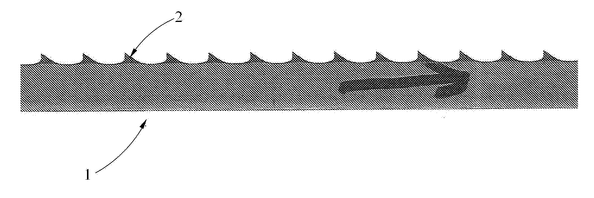
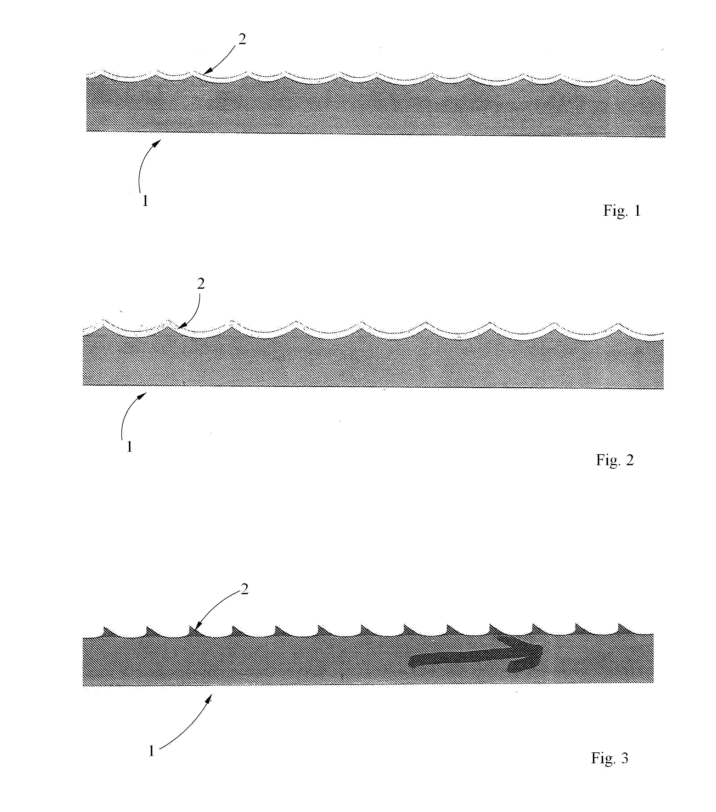
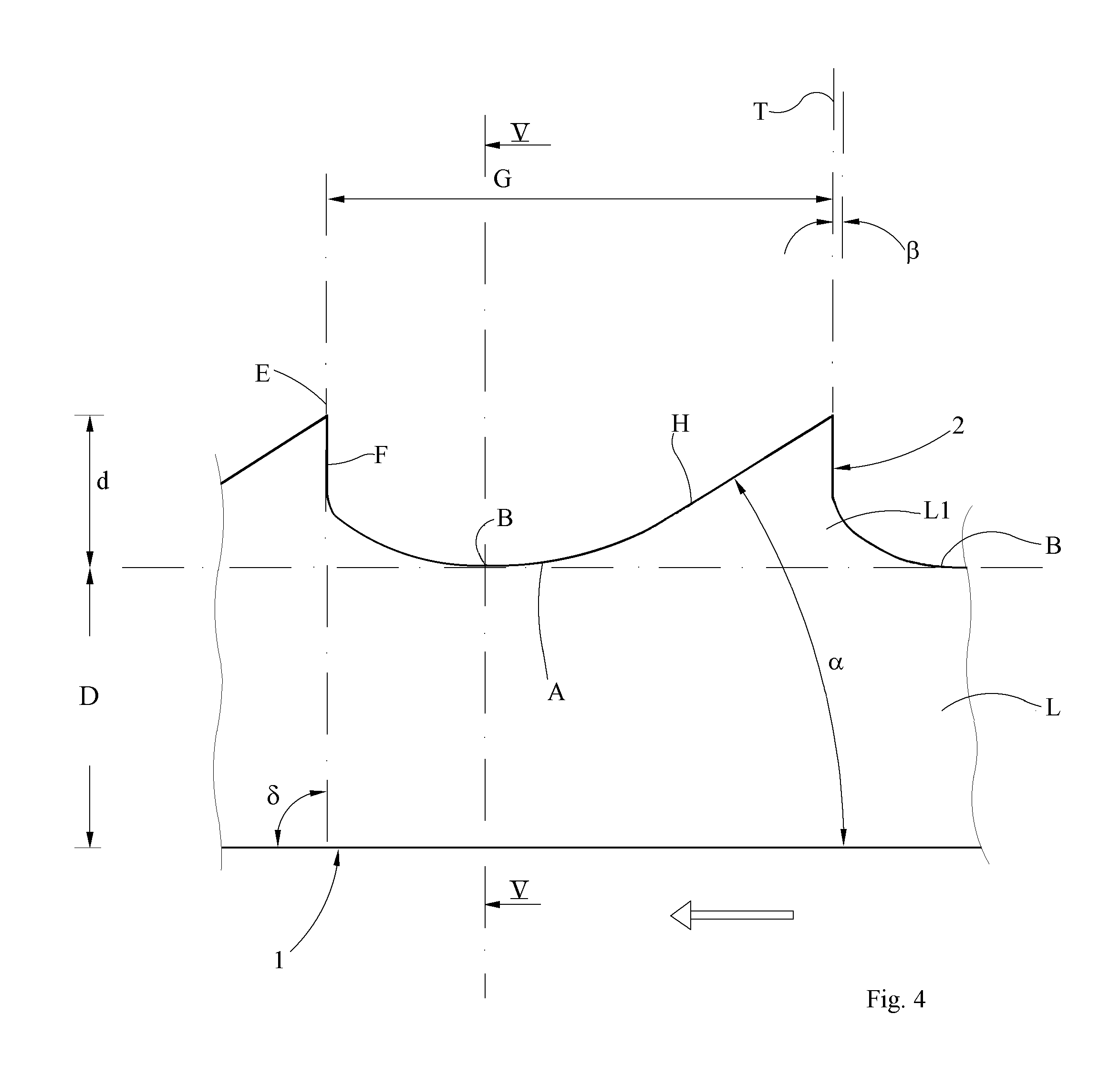
[0018]In FIGS. 3 to 5, a preferred embodiment of a bread-knife blade according to the invention is shown. The bread-knife blade is intended for use in a machine saw and has a given direction of motion, which is shown with an arrow in FIG. 3. The bread-knife blade has teeth 2 with a tooth edge E. At the front of each tooth 2 there is a tooth breast H, and behind the tooth edge E there is a tooth back F. A tooth bottom B extends between the tooth breast H and the tooth back F. The distance between two tooth edges

[0019]E constitutes a tooth gap G. The knife blade 1 has two flat sides, which, when the knife blade is regarded obliquely from above in the sawing direction, is defined as a right side R and a left side L.

[0020]A characteristic aspect of the invention in relation to known bread-knife blades is the asymmetric extension of the tooth breast H and the tooth back F i relation to a transverse line T. (Known blades normally have symmetry.) According to the invention, the asymmetry i...


PUM

PropertyMeasurementUnit
angleaaaaaaaaaa
angleaaaaaaaaaa
angleaaaaaaaaaa

Abstract

The present invention relates to a bread-knife blade for machine saws, which bread-knife blade (1) blade has teeth (2) with a tooth edge (E), a tooth breast (H) at the front of the tooth, seen in the sawing directing, a tooth back (F) behind the tooth edge (E), and a tooth bottom (B) between the tooth breast of each tooth and the tooth back of next tooth in front thereof, and tooth gaps, wherein a tooth gap (G) is defined as the space between the tooth edges (E) of two subsequent teeth (2), which knife blade has two flat sides (L, R), a right side (R) and a left side (L), when the knife blade is regarded obliquely from above in the sawing directing, wherein said tooth edge (E) consists of a point.

Description

TECHNICAL FIELD[0001]The present invention relates to a bread-knife blade for machine saws, which bread-knife blade has teeth with a tooth edge, a tooth breast at the front of the tooth, seen in the sawing directing, a tooth back behind the tooth edge, and a tooth bottom between the tooth breast on each tooth and the tooth back of the next tooth in front thereof, and tooth gaps, wherein a tooth gap is defined as the space between the tooth edges of two subsequent teeth, which knife edge has two flat sides, a right side and a left side, when the knife blade is regarded obliquely from above in the sawing directing, wherein said tooth edge consists of a point. The invention also relates to a method for the manufacture of a bread-knife blade.BACKGROUND[0002]Bread-knife blades for machine saws for industrial use have been a more and more important product as more and more consumers choose to buy ready-sliced bread. The machine equipment used is in principle similar to a traditional machi...

Claims


Application Information

Patent Timeline
Patent Type & Authority Applications(United States)
IPC IPC(8): B24B3/58B26D1/00
CPCB24B3/586B26D2001/006B26D2001/0053B26D1/0006B24B3/54B24B19/002B24B19/02B26D2210/06Y10T83/9365
Inventor HALLBERG, PER-OLOV
Owner MUNKFORSSAGAR
Why Eureka
Try Eureka