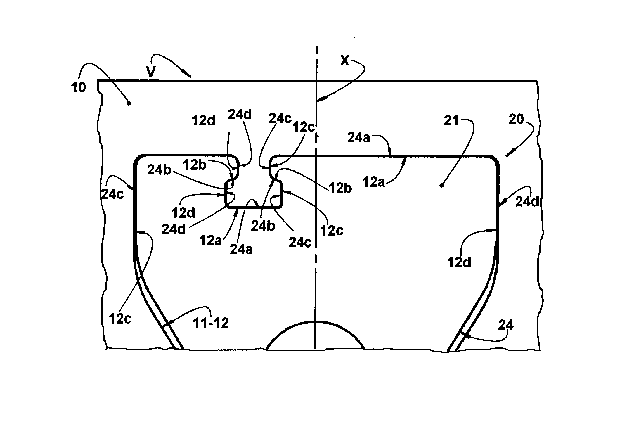
The need of a radial gap between the flexible vane 20 and the spacer body 10 provokes an undesirable increase of the
dead volume of the compressor, impairing its
volumetric efficiency.
However, it is necessary that the flexible vanes 20 present high
impact and bending strength, which can be obtained with the use of nobler materials, which must be applied not only to the flexible vane 20, but also to the spacer body 10, in a single-piece with the vane, undesirably increasing the cost of the single-piece suction valve V.
Nevertheless, considering that the flexible vane must be mounted between the confronting face of the valve plate and the sealing
gasket to be seated against the block of the compressor, a problem occurs in that the sealing
gasket has to “absorb” the thickness of the flexible vane.
It should be noted that, although being compressible in its thickness, the sealing
gasket admits a degree of compression which is insufficient to absorb or compensate for the thickness of the flexible vane disposed between the compressor block and the confronting face of the valve plate.
If the depth of the recess is lower than the thickness of the flexible vane, and the sealing gasket is not capable to deform under compression, so as to absorb the “excess” of thickness of the flexible vane, the required sealing degree will not be reached, resulting in leaks in the compression chamber after mounting the parts of flexible vane, sealing gasket, valve plate and head to the compressor block.
On the other hand, when the depth of the recess is higher than the thickness of the flexible vane and the sealing gasket is not capable of compensating for this difference, there will occur leak in the compression chamber after mounting the parts responsible for the closing thereof.
Considering that the manufacturing thickness of the flexible vanes varies by about 0.005 mm, the processes for manufacturing the recess in the valve plate with this margin of tolerance tends to increase the cost of this solution.
Irregularities on the recess surface may impair the alignment between the fixing end portion of the flexible vane and the annular seat of the suction valve, which can generate leaks during operation of the compressor.
Besides, the finishing operations of surfaces presenting recesses can substantially increase the production costs, as compared with operations for finishing smooth surfaces, and even annul the advantages related to the vane-type suction valves.
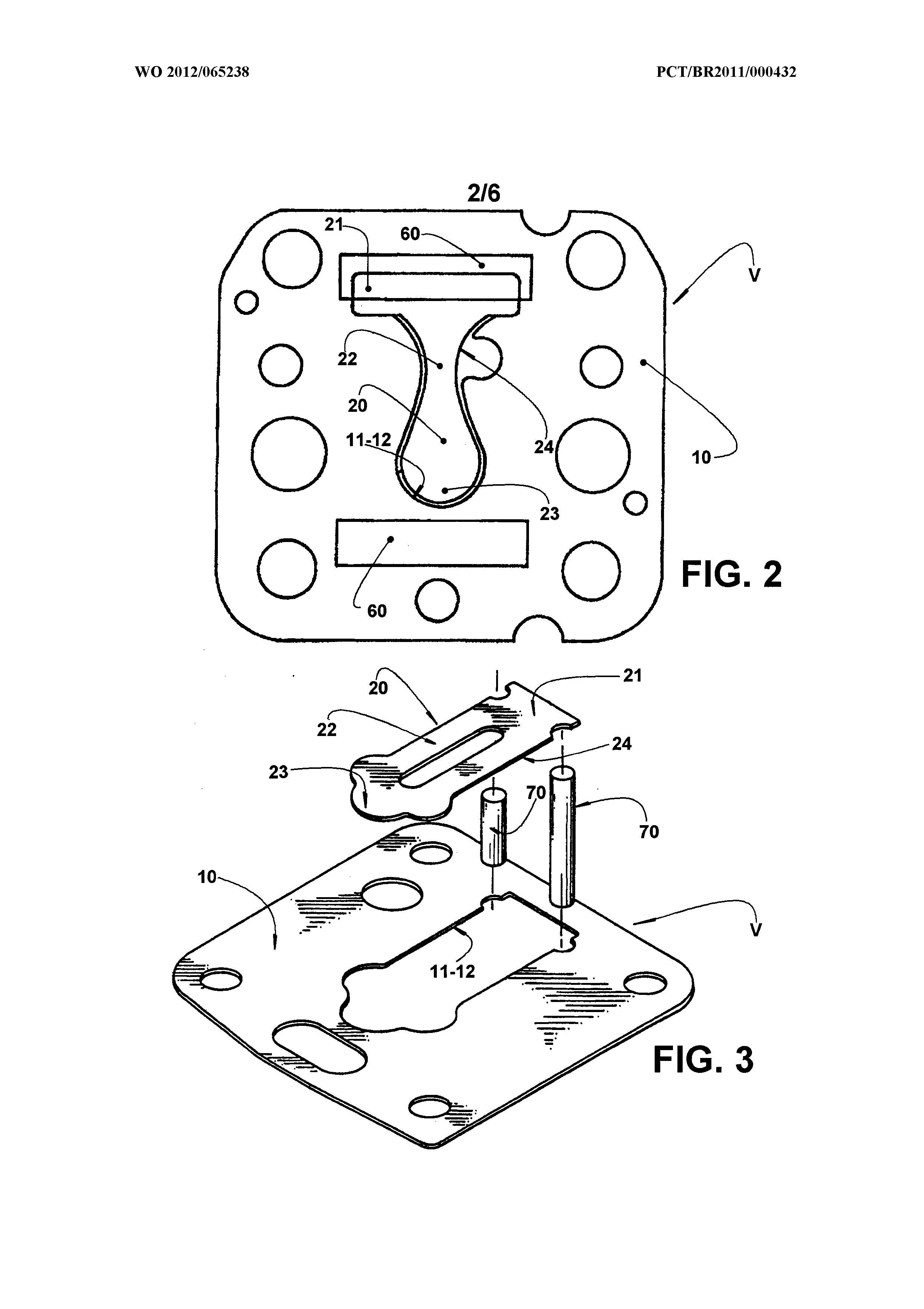
Nevertheless, although not presenting the limitations of the single-piece suction valve construction, which has two component-parts formed in a single piece, this solution comprising two different pieces presents the
disadvantage of requiring additional procedures and measures for joining the spacer body and flexible vane to each other, and then for mounting them to the valve plate, in order to guarantee the correct positioning of the flexible vane in the latter, before affixing the valve plate to the
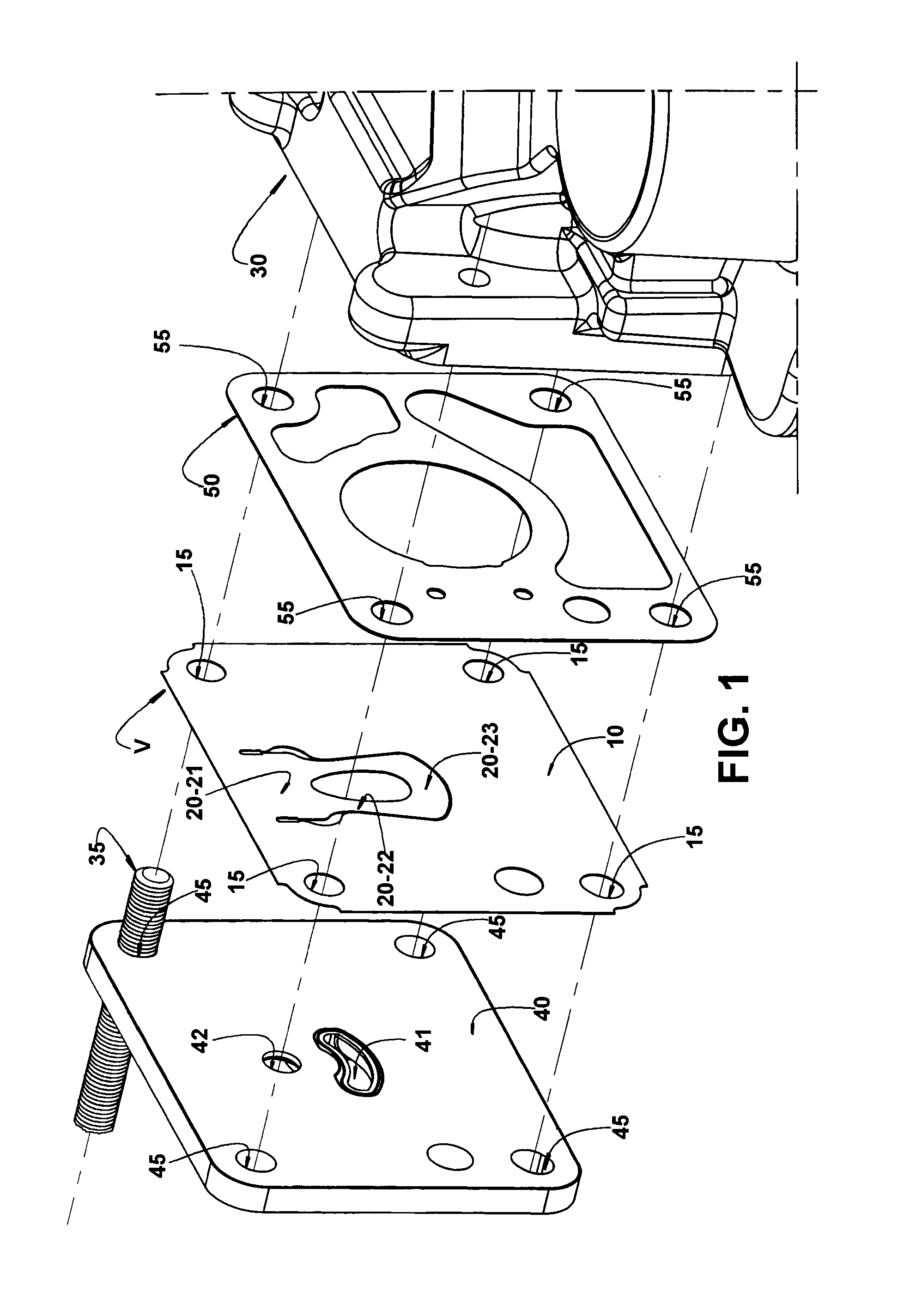
crankcase 30 (illustrated only in FIG.
This solution has the inconvenience of presenting cost increments related to the production of pins and holes for the fitting in the compressor block and in the valve plate, as well as to the complexity of the manufacturing and mounting processes.
The properties of the flexible vane cannot suffer physical or chemical alterations, after the joining process, at the risk of compromising its useful life.
Also during the joining process, it cannot occur excessive deposition of material which surpasses the nominal thickness of the
metal sheets which define the two valve pieces, which can cause leaks in the compression chamber, with harmful
impact on the efficiency of the compressor.
In short, the process for affixing the vane and the spacer body to each other requires several cares, and may compromise the reduction of cost obtained by using a less noble material in the spacer body.

