Motor and electric apparatus equipped with same

a technology of motor and electric apparatus, applied in the direction of dynamo-electric machines, magnetic circuit shapes/forms/constructions, supports/enclosements/casings, etc., can solve the problems of differences in electric potential between individual structural components, no measures have been taken against electrolytic corrosion, and abnormal noise, so as to reduce the voltage and influence, suppress the development of electrolytic corrosion, and avoid the effect of electrolytic corrosion

Active Publication Date: 2006-08-24
PANASONIC CORP
View PDF26 Cites 37 Cited by
  • Summary
  • Abstract
  • Description
  • Claims
  • Application Information

AI Technical Summary

Benefits of technology

[0014] This structure short-circuits and equalizes potentials between the stator core and the bracket by way of the conductive member, and substantially reduces a voltage impressed on the bearings, thereby suppressing development of electrolytic corrosion. As a result, this invention makes measures such as use of bearings with ceramic balls unnecessary, and it can thus provide the motor having means of avoiding the electrolytic corrosion with a comparatively simple structure at a low cost. In this structure, the conductive member exhibits a large effect when it short-circuits the bracket and the stator core at one side adjoining the printed wiring board.

Problems solved by technology

In employment of such PWM method of driving, it is likely that a phenomenon of wavelike wear occurs on bearings rotatably supporting a motor shaft when high-frequency electrolytic corrosion (“electrolytic corrosion”) has progressed, which may eventually cause abnormal noises.
In the above structure of the conventional motors of this kind, however, no measures had ever been taken against electrolytic corrosion.
These currents produce differences in electric potential among the individual structural components, and they consequently cause electrolytic corrosion under certain conditions.
If the above phenomenon continues over a long period of time, it may eventually result in electrolytic corrosion.
This phenomenon of electrolytic corrosion roughens the rolling surfaces of bearings 515, and eventually leads the motor to generate abnormal noises when repeated until the surfaces are worn into wavelike form.
However, the bearings provided with ceramic balls are very expensive, and they have not as yet come to wide use in mass production.
None of the above methods is entirely satisfactory, however, in view of the reliability, cost, quality and convenience of use, and they have not as yet been adopted for practical use.
The measures to prevent electrolytic corrosion thus entail an increase in cost of the bearings and materials of the motor, and a decrease in the convenience of use, as described above.

Method used


Image

  • Motor and electric apparatus equipped with same
  • Motor and electric apparatus equipped with same
  • Motor and electric apparatus equipped with same

Examples


first exemplary embodiment

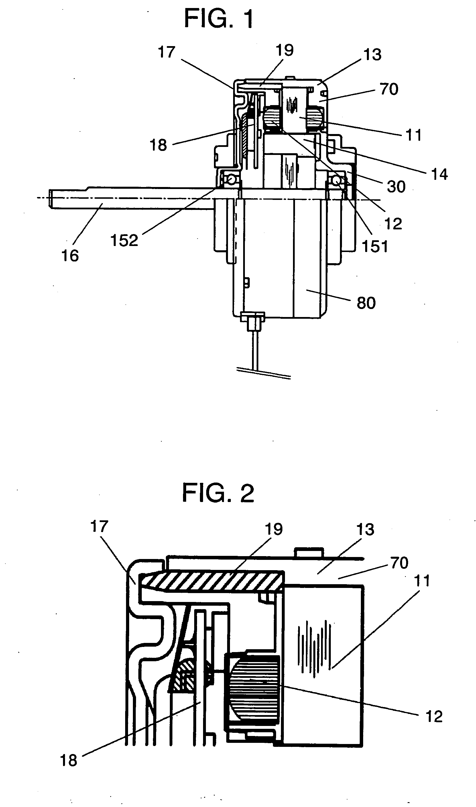
[0036]FIG. 1 is a partially sectioned structural view of a motor according to a first exemplary embodiment of this invention, and FIG. 2 is an enlarged sectional view showing a structure around a conductive pin (i.e., conductive member) shown in FIG. 1.

[0037] Motor 80 shown in FIG. 1 represents a fan motor for an indoor unit of an air conditioner (may be referred to hereinafter as “indoor unit motor”). In FIG. 1, motor 80 of this embodiment comprises stator 70 having stator core 11 and stator winding 12 wound on stator core 11 and integrally molded with insulation resin 13, rotor 14 provided with shaft 16, first bearing 151 and second bearing 152 for supporting shaft 16, bracket 17 connected to stator 70 and retaining at least one of first bearing 151 and second bearing 152, and conductive member 19 short-circuiting between stator core 11 and bracket 17.

[0038] Description is provided further of the structure of motor 80 in detail with reference to FIG. 1 and FIG. 2. Stator winding...

second exemplary embodiment

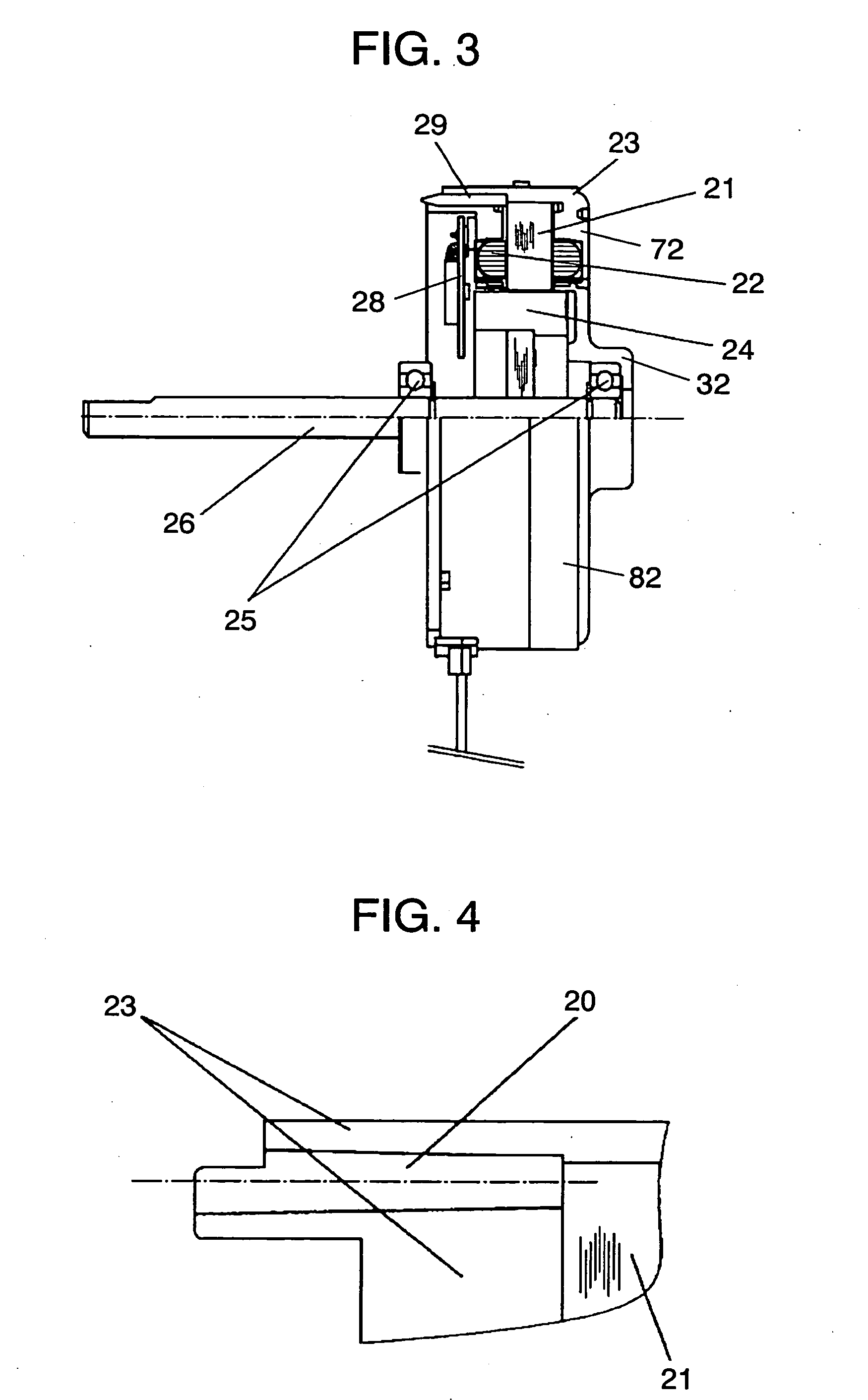
[0043]FIG. 3 is a partially sectioned structural view of a motor before a bracket is press-fitted according to a second exemplary embodiment of this invention, and FIG. 4 is an enlarged sectional view showing a structure around an insertion hole for a conductive pin (i.e., conductive member) shown in FIG. 3.

[0044] Stator winding 22 is wound on stator core 21 insulated with resin. Stator core 21 and stator winding 22 are integrally molded with insulation resin 23 to form stator 72. Printed wiring board 28 provided with a drive circuit for driving motor 82 is also molded together into one integral body in the same molding process. A complete molded body of stator 72 is thus composed with addition of printed wiring board 28. Insulation resin 23 used here is unsaturated polyester resin, that is a thermosetting plastic.

[0045] On the other hand, shaft 26 is press-fitted to rotor 24. In addition, two bearings 25 (i.e., first bearing and second bearing) are attached to shaft 26 for suppor...

third exemplary embodiment

[0050]FIG. 5 is a front view of a motor before a bracket is press-fitted according to a third exemplary embodiment of this invention, FIG. 6 a perspective view of a complete molded body (i.e., stator) according to the third exemplary embodiment, FIG. 7 an enlarged front view of a continuity check slit (i.e., notch) shown in FIG. 5, and FIG. 8 a front view of the motor shown in FIG. 5 after the bracket is press-fitted.

[0051] A stator winding is wound on stator core 31 insulated with resin. Stator core 31 and the stator winding are integrally molded with insulation resin 33 to form stator 73. Insulation resin 33 used here is unsaturated polyester resin, a kind of thermosetting plastic.

[0052] Bearing 35 is attached to shaft 36 of a rotor for supporting shaft 36 in a rotatable manner. After the rotor is assembled into stator 73, bracket 37 is press-fitted to stator 73 to complete motor 83. Motor 83 of this exemplary embodiment has such a structure that stator core 31 and bracket 37 ar...


PUM


Abstract

A motor comprises a stator having a stator core and a stator winding wound on the stator core and integrally molded with insulation resin, a rotor provided with a shaft, a first bearing and a second bearing for supporting the shaft, a bracket connected to the stator and retaining at least one of the first bearing and the second bearing, and a conductive member short-circuiting between the stator core and the bracket.

Description

TECHNICAL FIELD [0001] The present invention relates to a motor to be mounted to an electric apparatus such as an air-conditioning unit for driving a blower fan. BACKGROUND ART [0002] There is a demand in recent years for improvement in efficiency of fan motors mounted to air conditioners for driving blower fans, for instance, because of the trend of saving energy consumption of the air-conditioning units. There are often cases that highly efficient brushless motors are used for these fan motors in place of induction motors. And in many cases, these brushless motors are driven by inverters of Pulse Width Modulation (hereinafter referred to as “PWM method”) as the driving method. [0003] In employment of such PWM method of driving, it is likely that a phenomenon of wavelike wear occurs on bearings rotatably supporting a motor shaft when high-frequency electrolytic corrosion (“electrolytic corrosion”) has progressed, which may eventually cause abnormal noises. [0004] Among conventional...

Claims


Application Information

Patent Timeline
Patent Type & Authority Applications(United States)
IPC IPC(8): H02K11/00
CPCH02K5/15H02K11/0089H02K5/1732H02K11/40
Inventor NANBU, YASUOSENGOKUDANI, YOSHIKAZUKUMAGAI, YUJI
Owner PANASONIC CORP
Why Eureka
Try Eureka