Magnetic-field-generating apparatus and magnetic field orientation apparatus using it

a magnetic field and generating apparatus technology, applied in the direction of permanent magnets, magnetic bodies, basic electric elements, etc., can solve the problems of large cooling water to remove, large cost of generating a magnetic field, and restricted installation sites on floors with small strength, and achieve good magnetic field parallelity, increase the weight of the magnetic field generating apparatus, and increase the effect of the weight of the permanent magn

Active Publication Date: 2004-12-30
HITACHI METALS LTD
View PDF8 Cites 35 Cited by
  • Summary
  • Abstract
  • Description
  • Claims
  • Application Information

AI Technical Summary

Benefits of technology

0062] Though a region with a small skew angle (good magnetic field parallelness) generally increases in the cylindrical hole in proportion to the longitudinal length of the magnetic-field-generating apparatus, the weight of permanent magnets used also increases, resulting in increase in the weight of the magnetic-fiel

Problems solved by technology

Accordingly, such a magnetic field-generating means uses large electric power, needing safety means and other facilities, and thus a large cost for generating a magnetic field and a large amount of cooling water to remove heat generated by large electric current.
Also, because this magnetic field-generating means comprises an iron core and an electromagnetic coil, it weighs 3 to 5 tons to generate a large magnetic field, resulting in restricted installation sites on floors with small strength.
Though the superconductive coil consumes less exciting current than an electromagnet, liquid nitrogen or helium should always be consumed to keep superconductivity, resulting in a high operation cost.
Also, in a system using a superconductive coil, the variation of a magnetic field turns superconductivity to normal conductivity locally, resulting in heat generation in the coil, and if this state were left to stand, the superconductivity of the entire apparatus would be destroyed.
Accordingly, it seriously suffers from the problem of a leaked magnetic field like the electromagnet.
However, because this apparatus mostly serves to adjust a magnetic field distribution, it ge

Method used


Image

  • Magnetic-field-generating apparatus and magnetic field orientation apparatus using it
  • Magnetic-field-generating apparatus and magnetic field orientation apparatus using it
  • Magnetic-field-generating apparatus and magnetic field orientation apparatus using it

Examples


example 2

[0081] The magnetic-field-generating apparatus of the present invention was used in an apparatus for extrusion-molding permanent magnets in this Example.

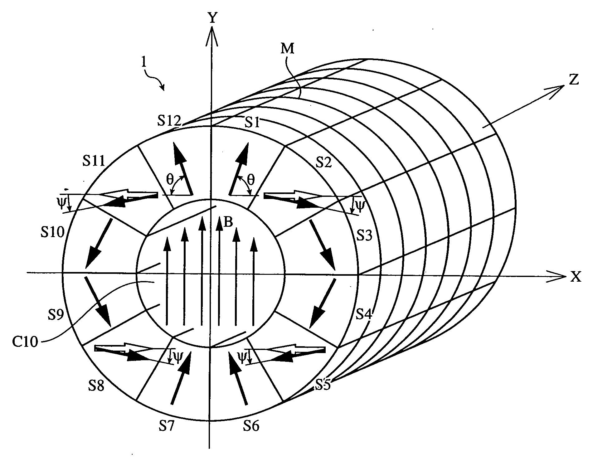
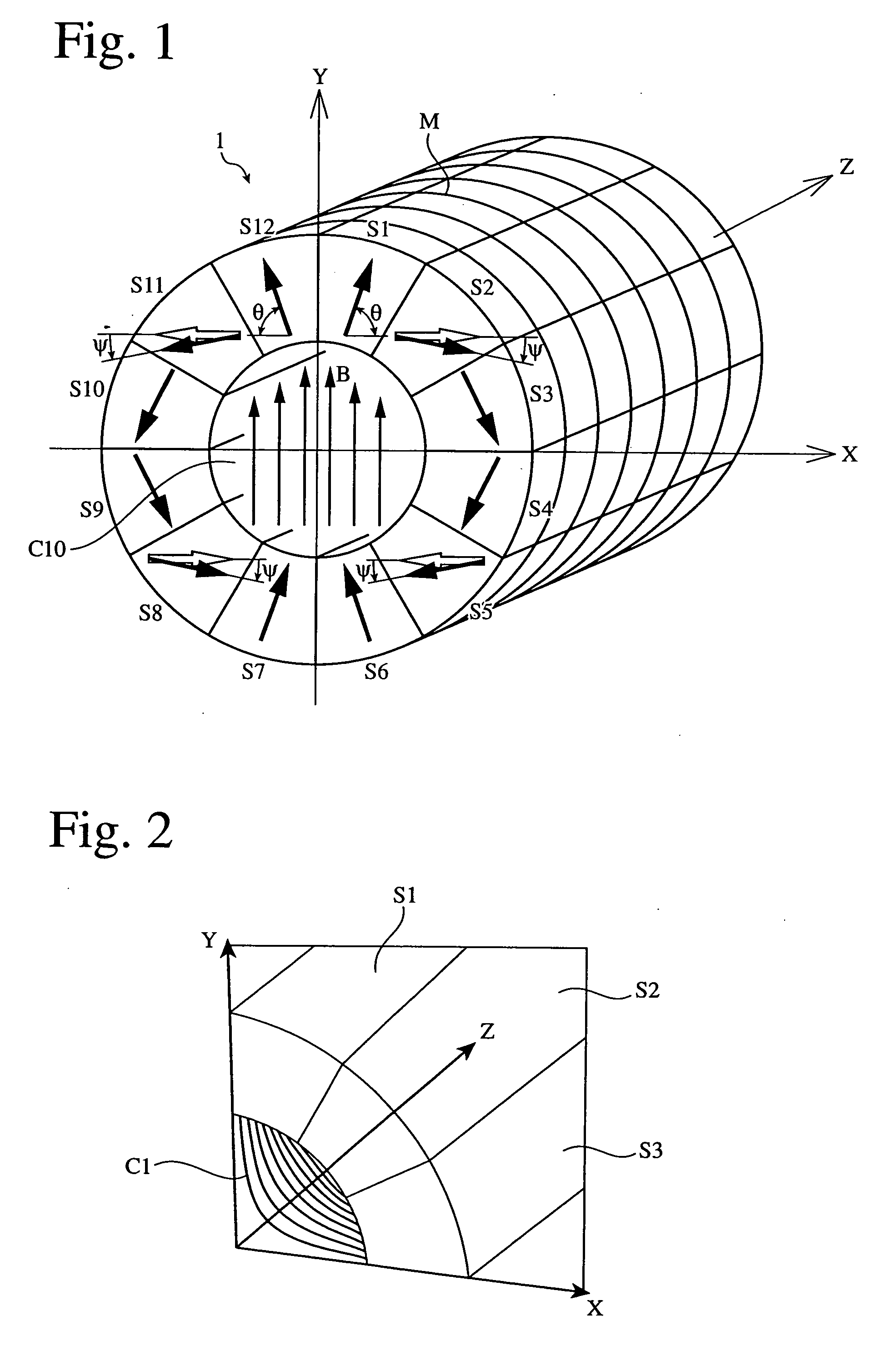
[0082] FIG. 14 shows one example of the apparatus of the present invention for extrusion molding in a magnetic field. Like Example 1, the magnetic-field-generating apparatus 10 comprised a 12-divided magnetic circuit, each segment being constituted by pluralities of sintered Nd--Fe--B permanent magnets having a residual magnetic flux density of 1.45 T and coercivity of 1192 kA / m. The magnetic circuit had an inner diameter D.sub.0 of 220 mm, an outer diameter D.sub.1 of 850 mm, and an axial length (length) H of 600 mm.

[0083] A starting material mixture mainly comprising magnet powder such as Nd--Fe--B rare earth magnet powder and a thermoplastic resin (for instance, polyamide resin) is thermally blended, and extrusion-molded in a magnetic field. This green body is magnetized along an anisotropy direction to obtain an anisotropic extr...


PUM


Abstract

An magnetic-field-generating apparatus comprising permanent magnet segments arranged to form a ring-shaped magnetic circuit having a center hole; adjacent permanent magnet segments having such different magnetization directions that their magnetization directions successively change along a circumferential direction of the magnetic circuit; a basic magnetization phase angle theta between the magnetization directions of the adjacent permanent magnet segments being 720/N (°); and a magnetization direction of at least one permanent magnet segment in an essential unit obtained by circumferentially dividing the ring to ¼ being deviated from the basic magnetization phase angle theta by such a deviating angle that a uniform magnetic flux flows in one direction along a diameter of the center hole.

Description

[0001] The present invention relates to an apparatus comprising pluralities of permanent magnets arranged in a ring shape with a center hole such that their magnetization directions are successively changed to generate a uniform, parallel magnetic field in the hole, and a magnetic field orientation apparatus comprising such a magnetic-field-generating apparatus, for instance, a furnace for heat-treating wafers with magnetic films in a magnetic field to orient the magnetic films in one direction, a die for magnetically orienting sintered permanent magnets and resin-bonded magnets so that they have magnetic anisotropy in the process of compression molding or extrusion molding, etc.[0002] A conventionally known apparatus for obtaining magnetic field strength without using exciting current is a Halbach-type magnetic circuit. This magnetic circuit is disclosed in "Journal of Applied Physics," Vol. 86, No. 11, Dec. 1, 1999, "Journal of Applied Physics," Vol. 64, No. 10, Nov. 15, 1988, and...

Claims


Application Information

Patent Timeline
IPC IPC(8): H01F7/20H01F13/00H01F41/02
CPCH01F7/202H01F13/003H01F41/0266H01F41/0273
Inventor KURIYAMA, YOSHIHIKOKIKUCHI, KEIKO
Owner HITACHI METALS LTD
Why Eureka
Try Eureka