
Fluidic zero-point power and propulsion units

a zero-point power and propulsion unit technology, applied in the direction of generator/motor, machine/engine, generator/motor, etc., can solve the problems of significant impediment, inability to demonstrate the casimir force convincingly, and failure to demonstrate the casimir effect (between two metal plates) successfully, so as to achieve the effect of higher energy

Inactive Publication Date: 2013-10-31
SHIVA SCI & TECH GRP
View PDF2 Cites 9 Cited by
  • Summary
  • Abstract
  • Description
  • Claims
  • Application Information

AI Technical Summary

Benefits of technology

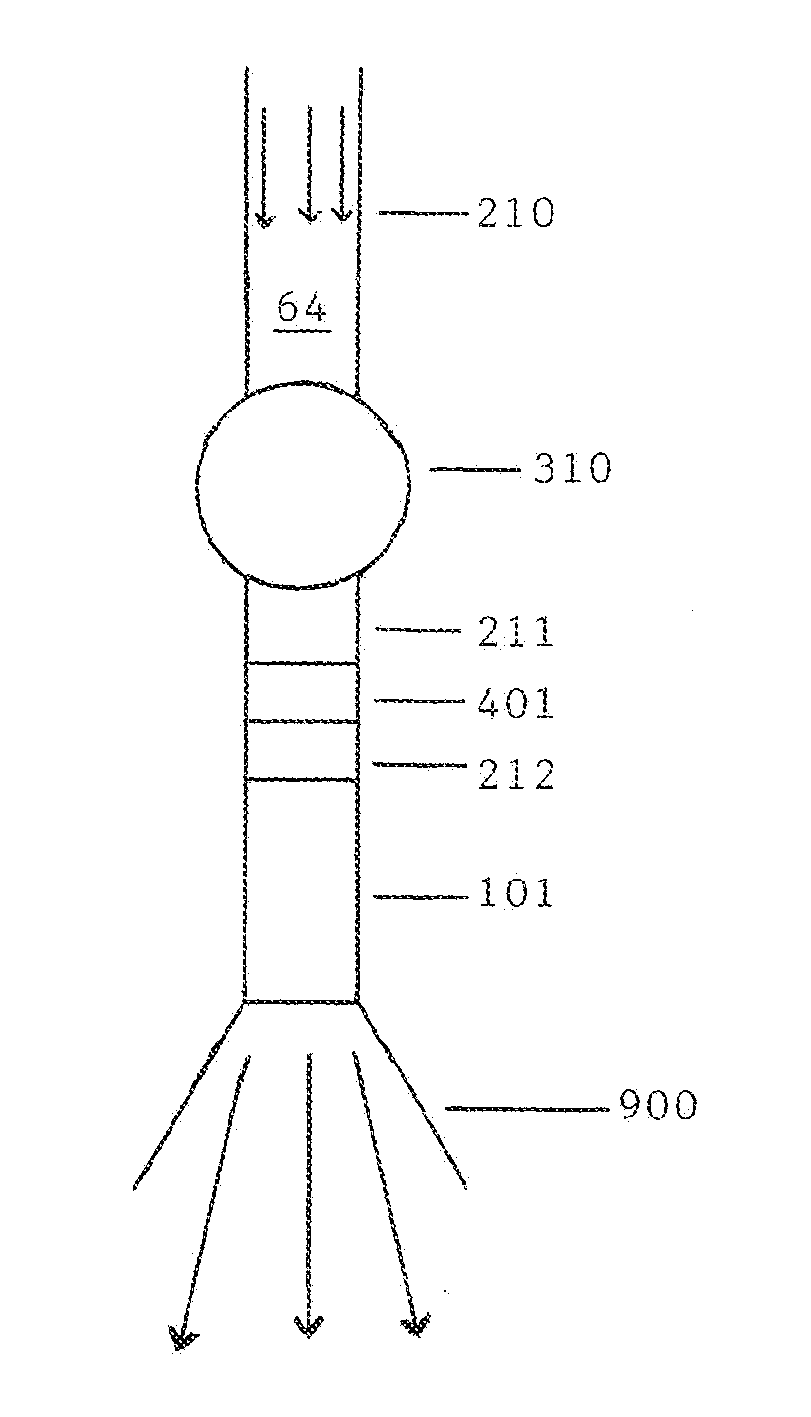
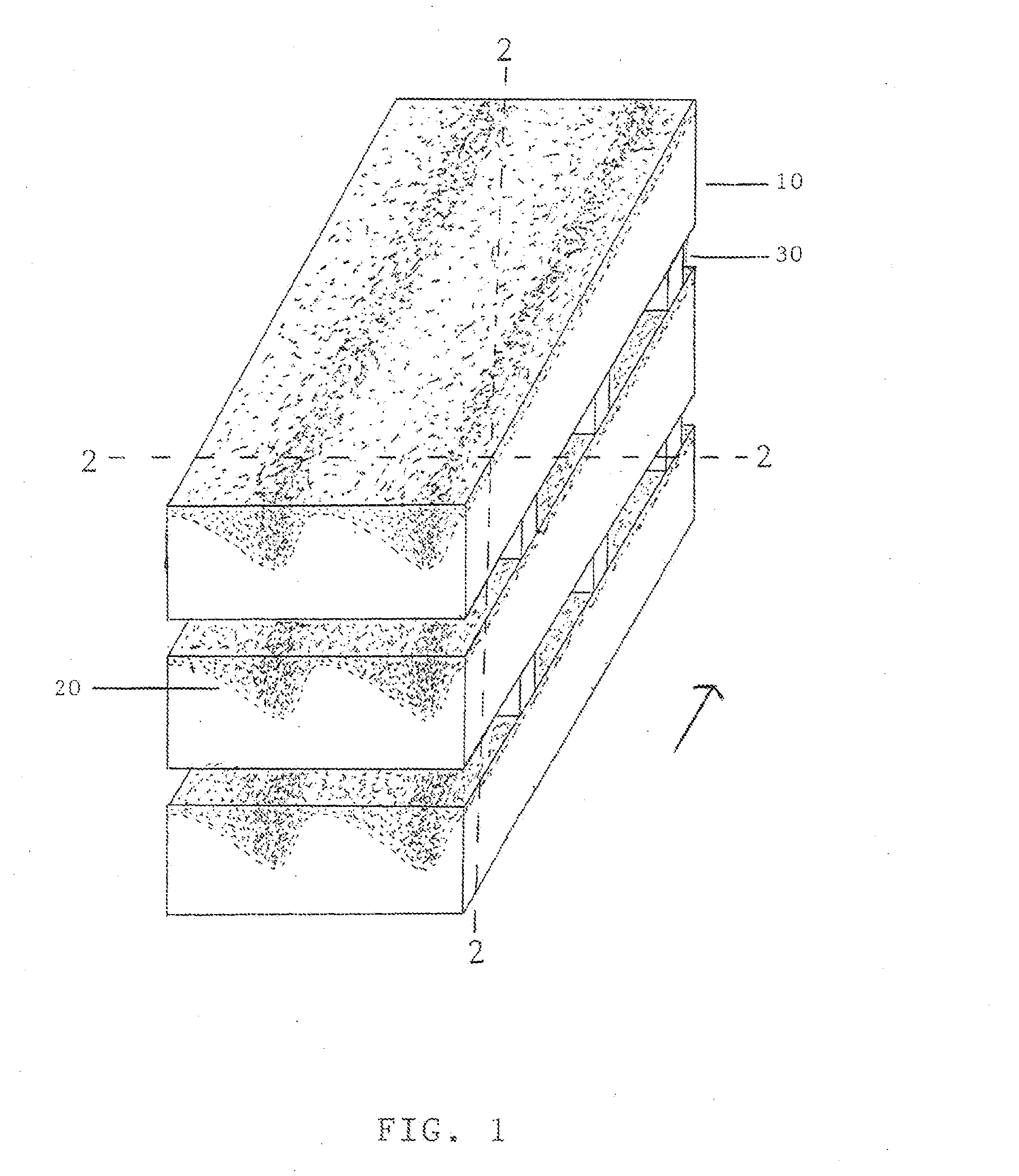
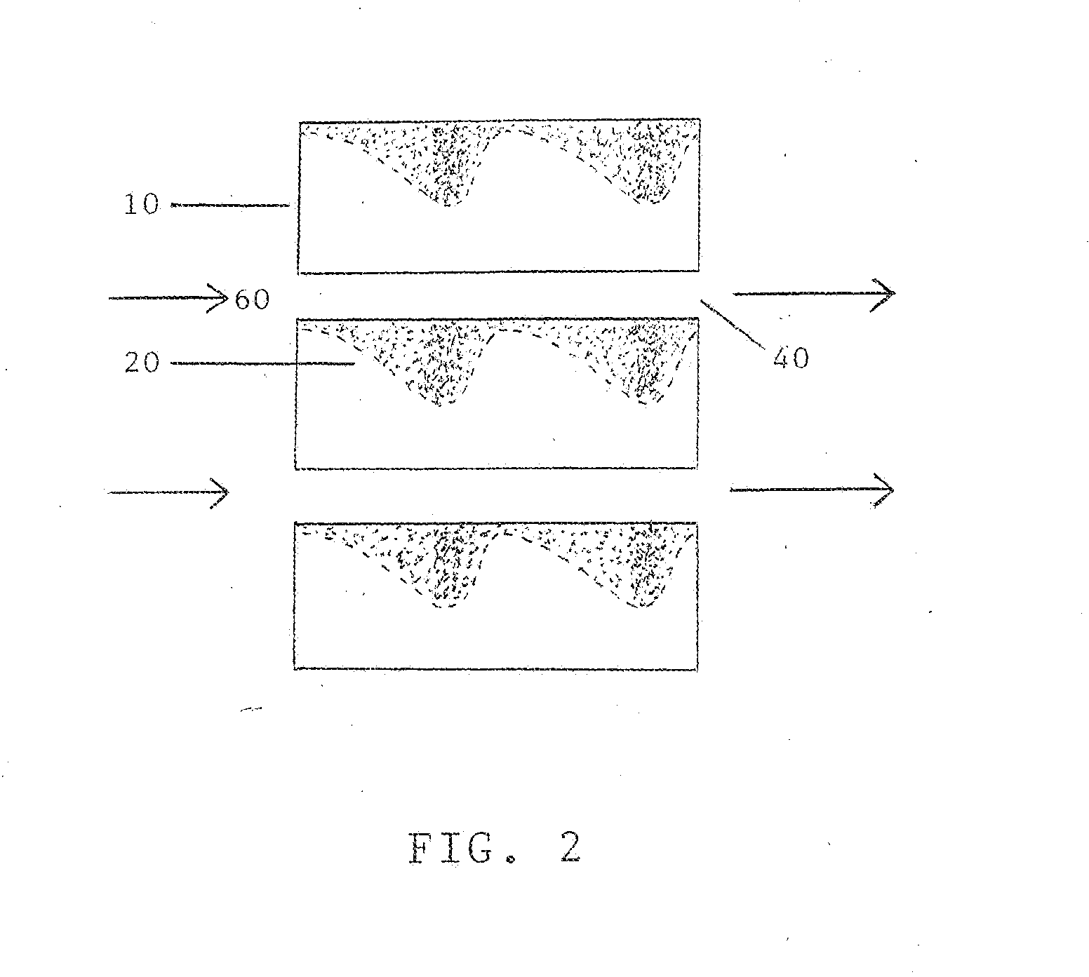
The present invention introduces practical devices that use CAM Technologies to accelerate fluids and expel them with higher energy. This is achieved by creating a gradient in the forces felt by the fluid inside the device. The exhaust fluid can be used for various purposes such as spinning turbines or providing thrust for propulsion. The force gradient can be created through different means and can be either continuous or discontinuous, linear or exponential in progression, and include a change in polarity.

Problems solved by technology

However, there are instances where boundary conditions result in an imbalance in these energies and a net force results.
This has been a significant impediment to their observation and quantification.
In fact, the Casimir force was not convincingly demonstrated until a 1997 experiment by S. K. Lamoreaux. Furthermore, the “classical” demonstration of the Casimir effect (between two metal plates) was not successfully demonstrated until a 2002 experiment by G. Bressi and others.
The devices and mechanisms described in the prior art given above are plagued with problems.
Many contain devices for which there simply is no economical method to manufacture.
Many would produce miniscule amounts of power at a relatively enormous cost.
And, in several instances, the envisioned devices simply could not work based upon what is now known of Casimir-vdW forces (often ignoring the electromagnetic behavior, usually including the absorbance spectra and spectral dielectric response, of real materials).

Method used


Image

  • Fluidic zero-point power and propulsion units
  • Fluidic zero-point power and propulsion units
  • Fluidic zero-point power and propulsion units

Examples


Embodiment Construction

[0038]Before the invention is described in detail, it is to be understood that, unless otherwise indicated, this invention is not limited to particular embodiments, materials, and processes, as such may vary. It is also to be understood that the terminology used herein is for purposes of describing particular embodiments only, and is not intended to be limiting.

[0039]As used in the specification and the appended claims, the singular forms “a,”“an,” and “the” include plural referents unless the context clearly indicates otherwise.

[0040]In this specification and the appended claims, reference will be made to a number of terms that shall be defined to have the following meanings:

[0041]The terms “optional” or “optionally” mean that the subsequently described feature or structure may or may not be present, or that the subsequently described event or circumstances may or may not occur, and that the description includes instances where a particular feature or structure is present and insta...


PUM


Abstract

Disclosed are devices which provide a practical means of extracting energy from the electromagnetic zero-point energy which permeates the universe. This is done by exploiting the Casimir-van der Waals' forces to accelerate a fluid through the device and exhaust it with a higher velocity and energy than that with which it entered. This kinetic energy gained by the fluid may then be used to do work, such as spin a turbine for power generation, or provide thrust for direct propulsion. These devices do not consume fuel nor any non-renewable resources during operation and they are capable of generating significantly more energy than they require to start or to be manufactured.

Description

CROSS-REFERENCE TO RELATED APPLICATIONS[0001]This application claims the priority benefit under 35 USC 119(e) from Provisional Application No. U.S. 61 / 850,343, “Zero-point power, propulsion, and catalysis units,” filed Feb. 13, 2013 and which is, in part, incorporated herein.STATEMENT REGARDING FEDERALLY SPONSORED RESEARCH OR DEVELOPMENT[0002]Not applicable.[0003]REFERENCE TO SEQUENCE LISTING, A TABLE, OR A COMPUTER PROGRAM LISTING COMPACT DISC APPENDIX[0004]Not applicable.FIELD OF THE INVENTION[0005]The present invention relates to energy producing devices which accelerate a fluid through the exploitation of Casimir-van der Waals forces (“Casimir-vdW forces”).BACKGROUND OF THE INVENTION[0006]Quantum field theory holds that the free space vacuum holds an infinite electromagnetic energy since each point in space may have an electromagnetic energy no less than the sum of one-half of the products of Planck's constant (h) and all frequencies of electromagnetic radiation possible at that...

Claims


Application Information

Patent Timeline
Patent Type & Authority Applications(United States)
IPC IPC(8): F01B29/00
CPCF01B29/00F03H99/00H02N11/008
Inventor BRESSI, ANTHONY DAVID
Owner SHIVA SCI & TECH GRP
Learn More