Method for operating a soot sensor

Inactive Publication Date: 2013-10-31
CONTINENTAL AUTOMOTIVE GMBH
View PDF12 Cites 12 Cited by
  • Summary
  • Abstract
  • Description
  • Claims
  • Application Information

AI Technical Summary

Benefits of technology

[0023]However, it is also advantageous if the point in time at which the carbon particulate sensor is burned clean is achieved during low load points of the internal combustion engine. In the case of a low load, the amount of

Problems solved by technology

In the case of a completely cooled internal combustion engine, conditions that render it almos

Method used


Image

  • Method for operating a soot sensor
  • Method for operating a soot sensor
  • Method for operating a soot sensor

Examples


Embodiment Construction

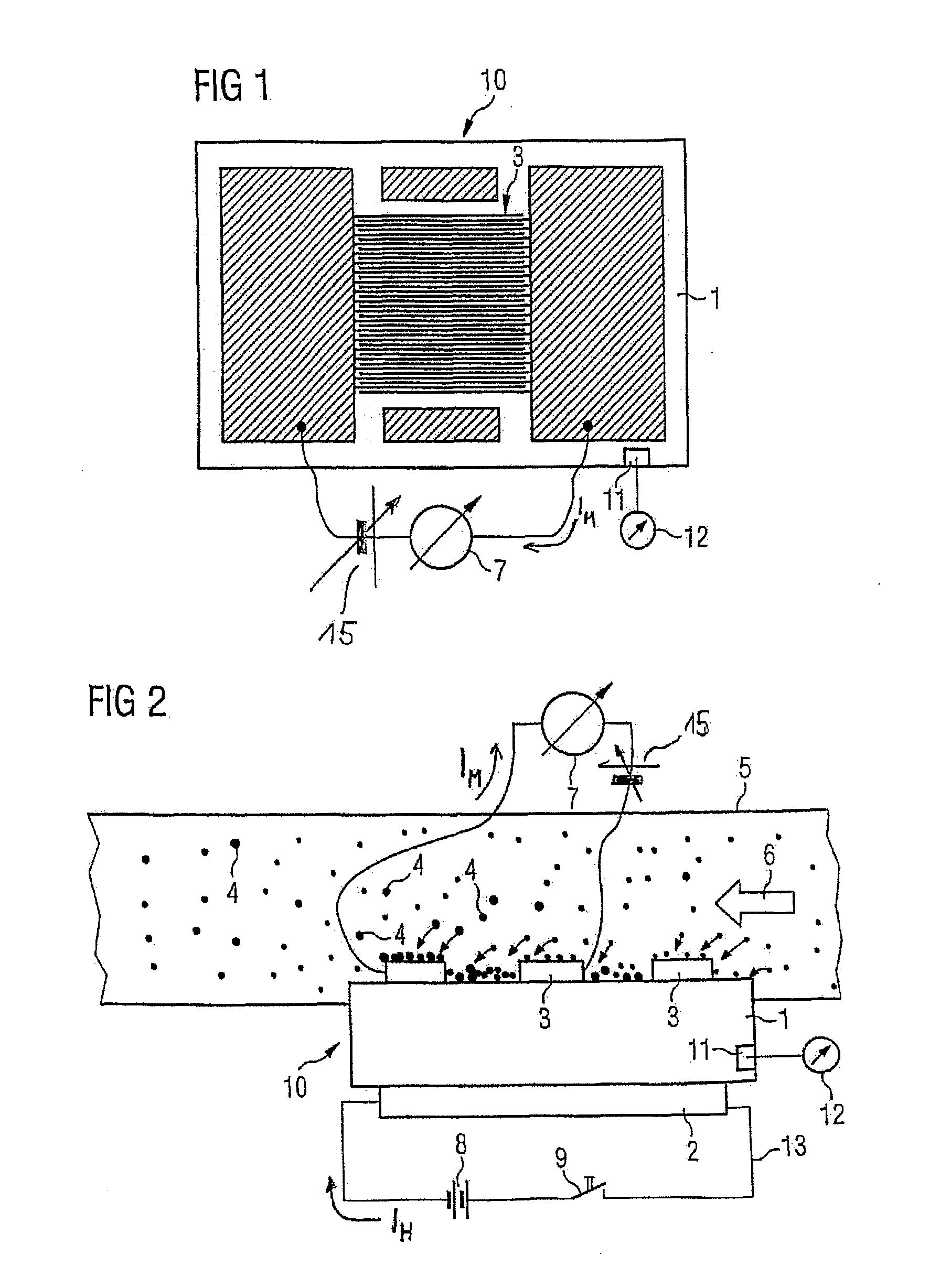
[0030]FIG. 1 illustrates a carbon particulate sensor 10 that is embodied from a molded body 1, a heating element 2, and a structure of measuring electrodes 3 that engage one with the other in an interleaved finger manner. The molded body 1 can be produced from a ceramic material or can be embodied from a different material that comprises electrically insulating properties and resists the temperatures involved when burning off carbon particulates 4. In order to burn off the carbon particulates 4 from the carbon particulate sensor 10, the carbon particulate sensor 10 is heated to temperatures between 500° C. and 800° C. in a typical manner with the aid of an electrical resistance heater. The electrically insulating molded body 1 must be able to withstand these temperatures without being damaged. The structure of the measuring electrodes 3 is embodied in this case by way of example as a mesh-like structure that is also described as an interleaved finger electrode structure 3, wherein a...


PUM


Abstract

A method for operating a soot sensor in the exhaust gas tract of an internal combustion engine. The soot sensor includes an inter-digital electrode structure to which a measurement voltage is applied. Soot particles from the exhaust gas flow deposit themselves on the inter-digital electrode structure and an measuring current is evaluated as a measurement for the soot concentration of the soot sensor. A heating element for burning clean the inter-digital electrode structure is provided. The method for operating the soot sensor has good measurement results and the shortest possible idle time. To this end, a point in time for burning clean the soot sensor is determined in accordance with the operational state of the internal combustion engine and then, the burning clean of the inter-digital electrode structure starts by heating the soot sensor by the heating element.

Description

CROSS REFERENCE TO RELATED APPLICATIONS[0001]This is a U.S. national stage of application No. PCT / EP2011 / 072778, filed on 14 Dec. 2011. Priority is claimed on German Application No.: 10 2010 054 671.2 filed 15 Dec. 2010 the content of which is incorporated here by reference.BACKGROUND OF THE INVENTION[0002]1. Field of the Invention[0003]The invention relates to a method for operating a carbon particulate sensor in the exhaust gas tract of an internal combustion engine. The carbon particulate sensor comprises an interleaved finger electrode structure to which a measuring voltage is applied. Carbon particulates from an exhaust gas flow deposit themselves on the interleaved finger electrode structure and the measuring current that flows over the carbon particulates and the interleaved finger electrode structure is evaluated as a measurement for the carbon particulate concentration of the carbon particulate sensor. The carbon particulate sensor comprises a heating element for burning cl...

Claims


Application Information

Patent Timeline
IPC IPC(8): G01N15/06
CPCG01N15/0656F01N9/002F01N2560/05Y02T10/40
Inventor ANTE, JOHANNESHERRMANN, MARKUSOTT, ANDREASREITMERIER, WILLIBALDSCHADLICH, DENNYWEIGL, MANFREDWILDGEN, ANDREAS
Owner CONTINENTAL AUTOMOTIVE GMBH
Why Eureka
Try Eureka