
Method of Fabricating Tunnel Transistors With Abrupt Junctions

a tunnel transistor and junction technology, applied in semiconductor devices, diodes, electrical apparatuses, etc., can solve the problems of high gate leakage, limit the improvement, and the difficulty of accurately controlling the undercut etching

Active Publication Date: 2013-10-31
IBM CORP
View PDF42 Cites 36 Cited by
  • Summary
  • Abstract
  • Description
  • Claims
  • Application Information

AI Technical Summary

Benefits of technology

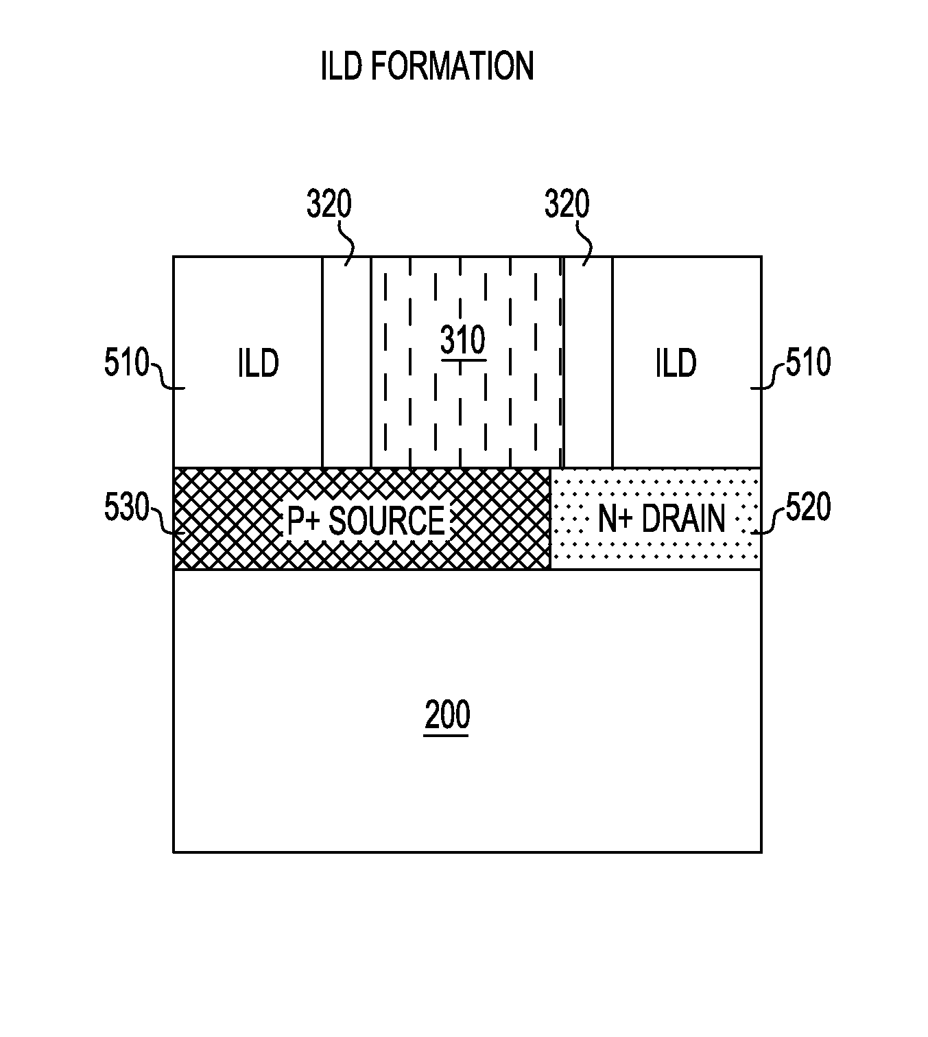
The invention provides a method for making a thin-based TFET device with a thin layer of material between the source, body, and drain regions. This thin layer can be modulated by the gate. The invention also introduces two types of TFET designs, including vertical and lateral TFETs. The invention also describes a process for forming a self-aligned etch cavity for BTBT using a replacement gate approach. The invention further describes tuning the crystal direction in which BTBT takes place by varying the shapes of the self-aligned etch cavity. The invention also provides a method for manufacturing a TFET with a thin epitaxial channel region, a replacement gate stack, sidewall spacers, and a thin epitaxial layer covering at least the source region. Overall, the invention improves the performance and efficiency of TFET devices.

Problems solved by technology

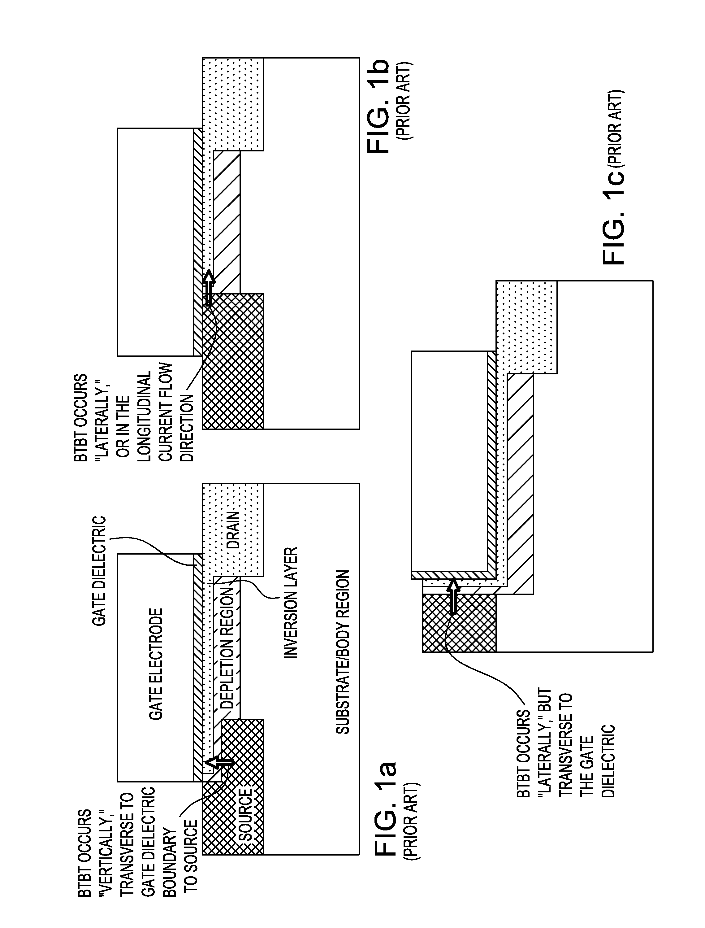
The limitation of the improvement is mainly related to the use of an isotropic etch to undercut the gate electrode.
Since it is desirable to place the Ge directly under the gate dielectric, the gate dielectric ends up being exposed to the isotropic etch, exposing to damage the gate dielectric and lead to high gate leakage.
Additionally, there is also a challenge of accurately controlling the undercut etch, since the extent of gate overlap of the Ge source region will determine how much BTBT can be modulated.
Engineering the BTBT barrier effectively is not easily achieved in order to obtain that the tunnel probability in the band edge overlap region be effectively 100%.
The limitation of this embodiment is that no integration scheme is forthcoming for actually building the device.
The limitation with this device structure is the same as with all other “vertical” transistor designs, wherein the gate-to-source parasitic capacitance is very high, due to the gate electrode and source regions both covering the same, large, area.
However, this structure is limited by the described integration scheme, wherein the Ge epitaxy is formed against the dielectric sidewall region.
It is well-known that semiconductor epitaxy against a dielectric sidewall (e.g., raised source / drain epitaxy in conventional MOSFETs) results in faceting and reduced epitaxial film quality along the dielectric sidewall.
In the context of a TFET, this will lead to a significant degradation in performance due to the presence of crystalline defects in the epitaxial region.

Method used


Image

  • Method of Fabricating Tunnel Transistors With Abrupt Junctions
  • Method of Fabricating Tunnel Transistors With Abrupt Junctions
  • Method of Fabricating Tunnel Transistors With Abrupt Junctions

Examples


Embodiment Construction

[0033]Detailed embodiments of the methods and structures of the present disclosure are described herein; however, it is to be understood that the disclosed embodiments are merely illustrative of the described methods and structures that can be embodied in various forms. In addition, each of the examples given in connection with the various embodiments of the disclosure is intended to be illustrative, and not restrictive. Further, the FIGs. are not necessarily to scale, some features can be exaggerated to show details of particular components. Therefore, specific structural and functional details disclosed herein are not to be interpreted as limiting, but merely as a representative basis for teaching one skilled in the art to variously employ the methods and structures of the present disclosure. For purposes of the description hereinafter, the terms “upper”, “lower”, “top”, “bottom”, and derivatives thereof shall relate to the disclosed structures, as they are oriented in the drawing...


PUM


Abstract

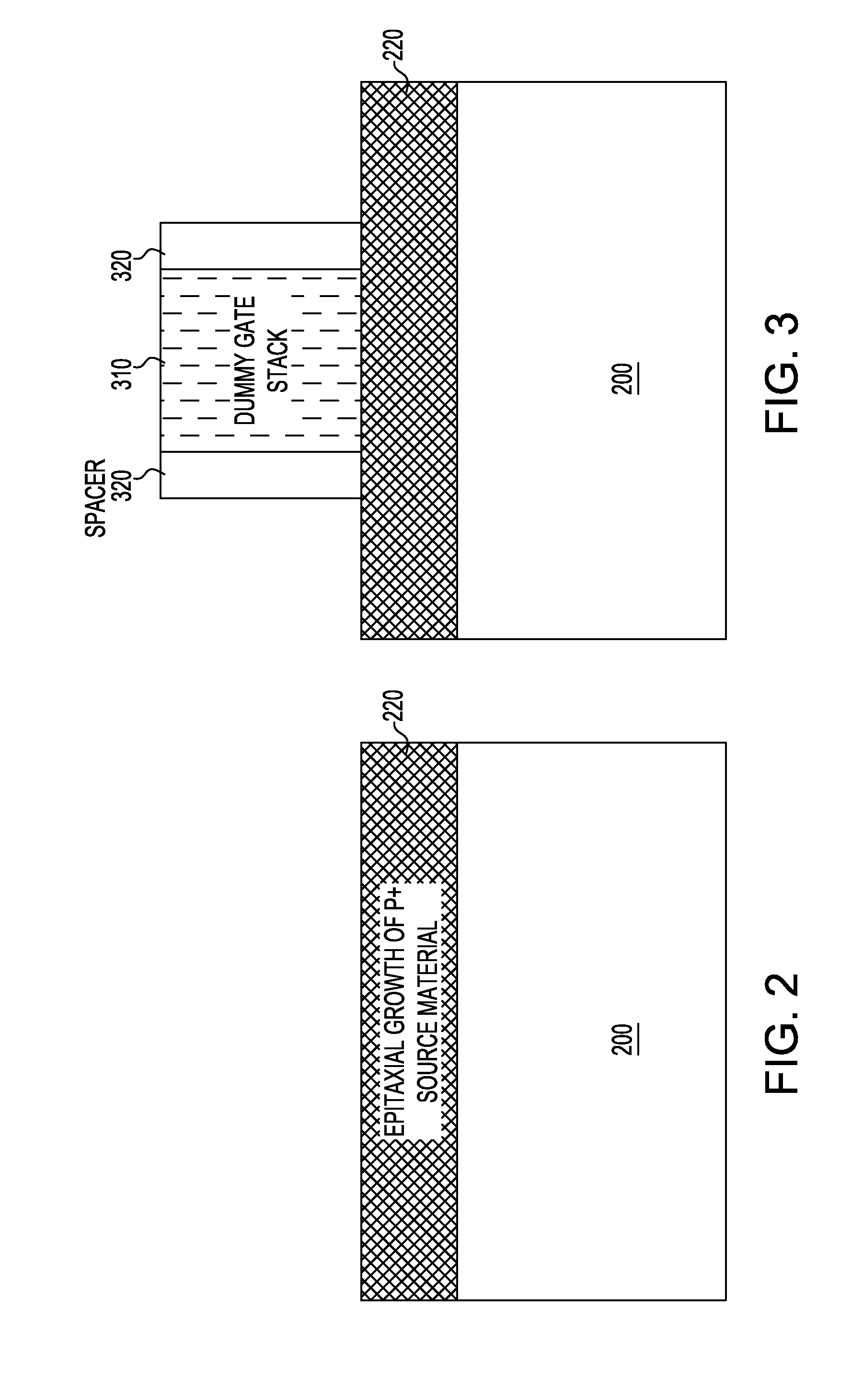
A method of manufacturing a tunnel field effect transistor (TFET) includes forming on a substrate covered by an epitaxially grown source material a dummy gate stack surrounded by sidewall spacers; forming doped source and drain regions followed by forming an inter-layer dielectric surrounding the sidewall spacers; removing the dummy gate stack, etching a self-aligned cavity; epitaxially growing a thin channel region within the self-aligned etch cavity; conformally depositing gate dielectric and metal gate materials within the self-aligned etch cavity; and planarizing the top surface of the replacement metal gate stack to remove the residues of the gate dielectric and metal gate materials.

Description

FIELD OF THE INVENTION[0001]The present invention relates to semiconductors devices, and more particularly, to junction tunnel transistors (TFETs) with controllable gate overlap and abrupt junctions as part of a replacement gate process flow and a method of manufacturing the same.BACKGROUND OF THE INVENTION[0002]Tunnel FETs have shown to be an alternative transistor design applicable to very low voltage operations. TFETs are a different type of transistor than conventional, thermal MOSFETs, because in TFETs a tunnel energy barrier is modulated at the source region, as opposed to a thermal barrier at the source region. It is the modulation of this tunnel barrier (in particular, a band-to-band tunnel (BTBT) barrier) which results in a drain-current-to-gate-voltage sensitivity (i.e, sub-threshold swing or SS) which can be superior to that in thermal MOSFETs. In thermal MOSFETs, the thermal limit for SS is defined as n*k*T*ln(10), where k is Boltzman's constant, T is the temperature (in...

Claims


Application Information

Patent Timeline
IPC IPC(8): H01L29/78H01L21/336
CPCH01L21/28079H01L21/28088H01L21/28114H01L21/28194H01L29/66356H01L29/7391H01L29/0684H01L29/78
Inventor VEGA, REINALDO A.ALPTEKIN, EMRETRAN, HUNG H.YUAN, XIAOBIN
Owner IBM CORP
Learn More