Image recognition device, image recognition method, and image recognition program
a technology of image recognition and image processing, applied in the field of image recognition devices, image recognition methods, and image recognition programs, can solve the problems of difficult mounting (installing) processes in pcs (personal computers) with high-speed cpus, processes consuming operation processing time, and heavy calculation load, so as to improve the efficiency of image recognition
- Summary
- Abstract
- Description
- Claims
- Application Information
AI Technical Summary
Benefits of technology
Problems solved by technology
Method used
Image

Examples
first embodiment
[0100]In this embodiment, an on-board image recognition system which is mounted on a vehicle will be described as an example.
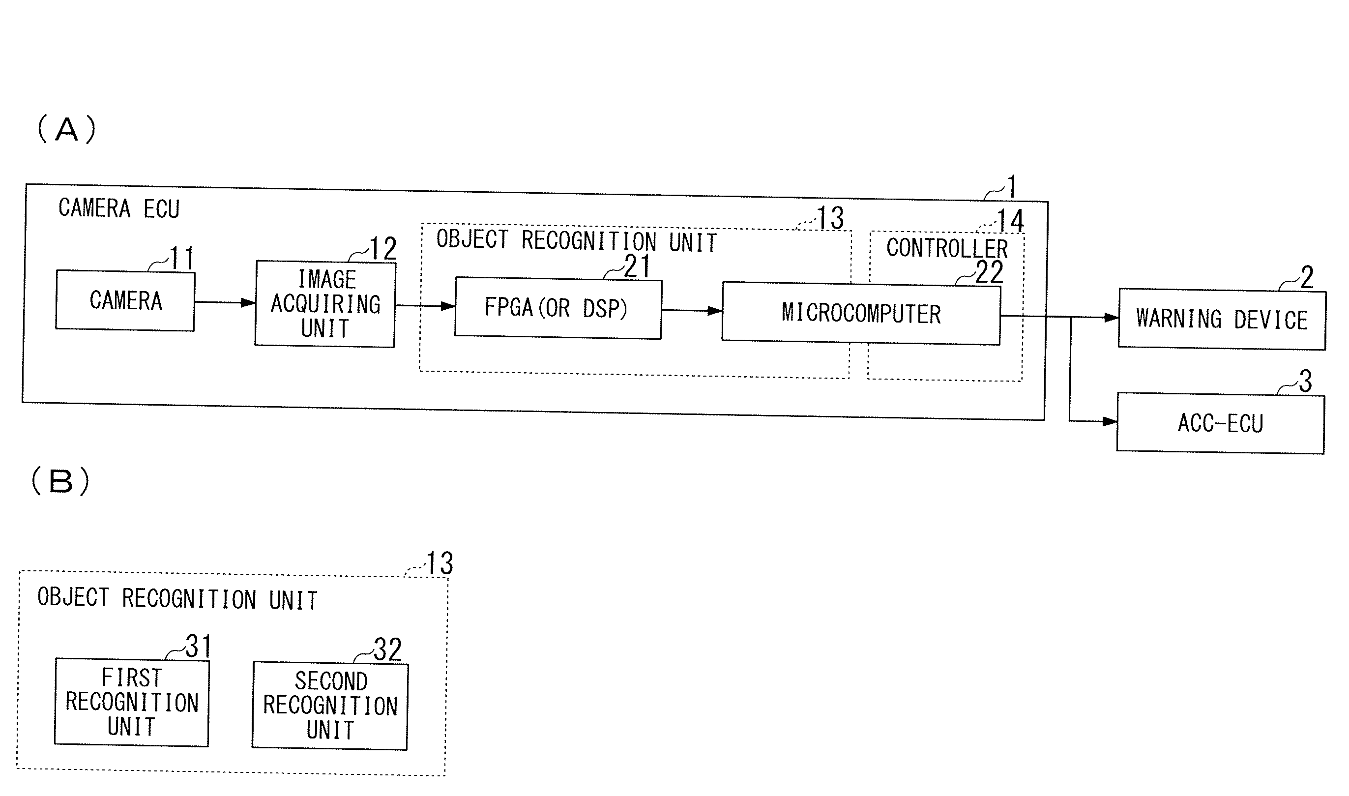
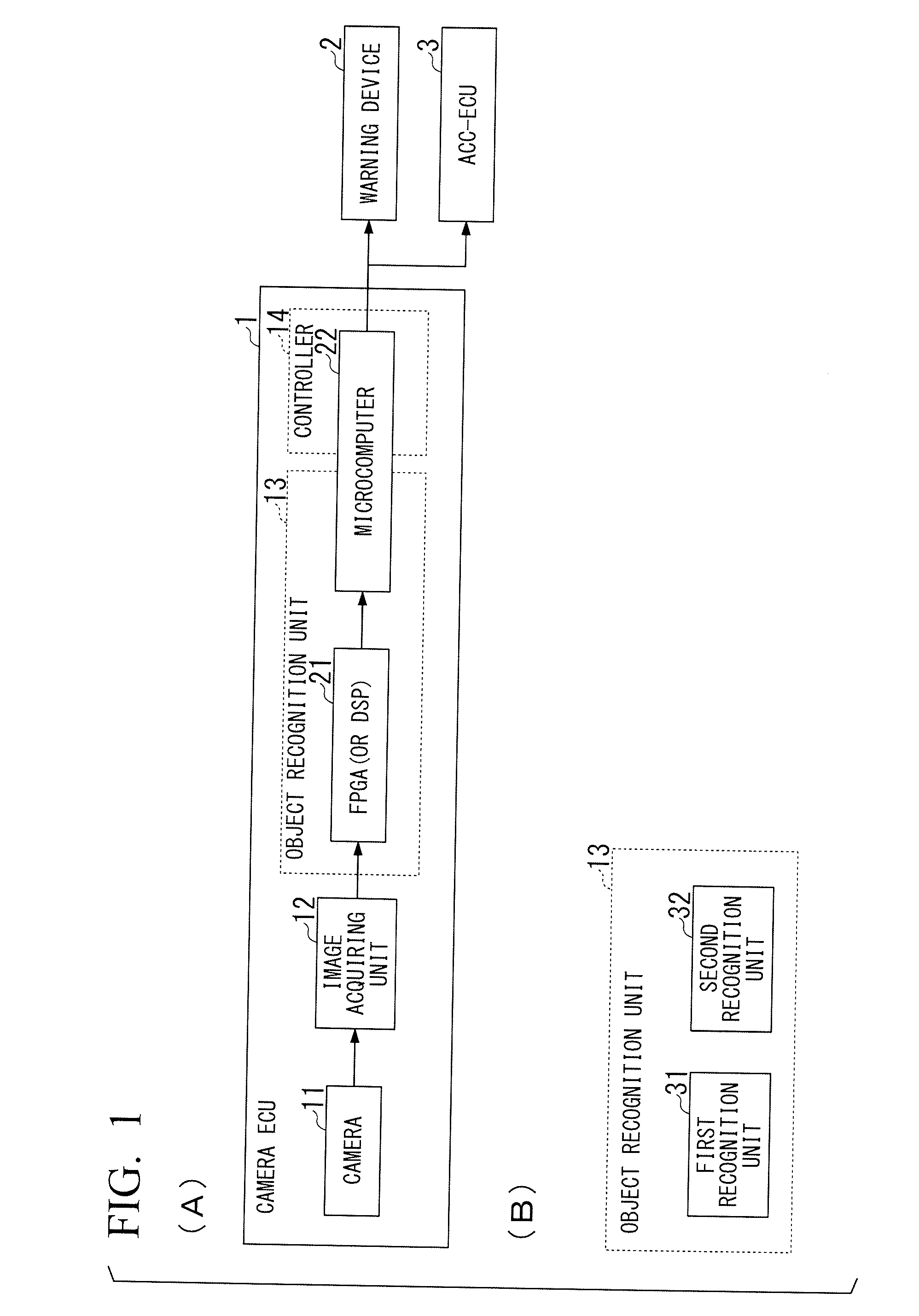
[0101]Part (A) of FIG. 1 is a block diagram schematically illustrating a configuration (hardware configuration) of an image recognition system according to an embodiment of the present invention.
[0102]The image recognition system according to this embodiment includes a camera ECU (Electronic Control Unit) 1, a warning device 2, and an ACC-ECU 3.
[0103]The camera ECU 1 is an example of an image recognition device.
[0104]The camera ECU 1 includes a camera 11, an image acquiring unit 12, an object recognition unit 13, and a controller 14.
[0105]In this embodiment, the object recognition unit 13 is constructed using the function of an FPGA (Field Programmable Gate Array) 21 and the function of a microcomputer 22.
[0106]The function of DSP (Digital Signal Processor) may be used instead of the function of the FPGA 21 or in addition to the function of the FPGA 21.
[0107]I...
second embodiment
[0375]The configuration of an image recognition system according to this embodiment is schematically the same as the configuration of the image recognition system according to the first embodiment shown in Part (A) of FIG. 1 and Part (B) of FIG. 1.
[0376]Accordingly, in this embodiment, the configuration will be described using the same reference numerals as shown in Part (A) of FIG. 1 and Part (B) of FIG. 1.
[0377]Hereinafter, differences from the first embodiment will be mainly described. Applicable details out of details described in the first embodiment may be applied to this embodiment.
[0378]A process flow which is performed by the object recognition unit 13 according to this embodiment will be described below with reference to FIG. 3.
[0379]FIG. 3 is a flowchart illustrating an example of a process flow which is performed by the object recognition unit 13 according to this embodiment.
[0380]When the processes of the flowchart according to this embodiment are roughly compared with ...
third embodiment
[0391]The configuration of an image recognition system according to this embodiment is schematically the same as the configuration of the image recognition system according to the first embodiment shown in Part (A) of FIG. 1 and Part (B) of FIG. 1.
[0392]Accordingly, in this embodiment, the configuration will be described using the same reference numerals as shown in Part (A) of FIG. 1 and Part (B) of FIG. 1.
[0393]Hereinafter, differences from the first embodiment will be mainly described. Applicable details out of details described in the first embodiment may be applied to this embodiment.
[0394]A process flow which is performed by the object recognition unit 13 according to this embodiment will be described below with reference to FIG. 4.
[0395]FIG. 4 is a flowchart illustrating an example of a process flow which is performed by the object recognition unit 13 according to this embodiment.
[0396]When the processes of the flowchart according to this embodiment are compared with the proc...
PUM
 Abstract
Description
Claims
Application Information
 - R&D
- Intellectual Property
- Life Sciences
- Materials
- Tech Scout
- Unparalleled Data Quality
- Higher Quality Content
- 60% Fewer Hallucinations
Browse by: Latest US Patents, China's latest patents, Technical Efficacy Thesaurus, Application Domain, Technology Topic, Popular Technical Reports.
© 2025 PatSnap. All rights reserved.Legal|Privacy policy|Modern Slavery Act Transparency Statement|Sitemap|About US| Contact US: help@patsnap.com