
Real-time pavement profile sensing system using air-coupled surface wave

a sensing system and real-time technology, applied in the direction of mechanical roughness/irregularity measurement, instruments, roads, etc., can solve the problem of extremely fast method, and achieve the effect of extremely fast method

Inactive Publication Date: 2013-10-31
NORTHEASTERN UNIV
View PDF18 Cites 10 Cited by
  • Summary
  • Abstract
  • Description
  • Claims
  • Application Information

AI Technical Summary

Benefits of technology

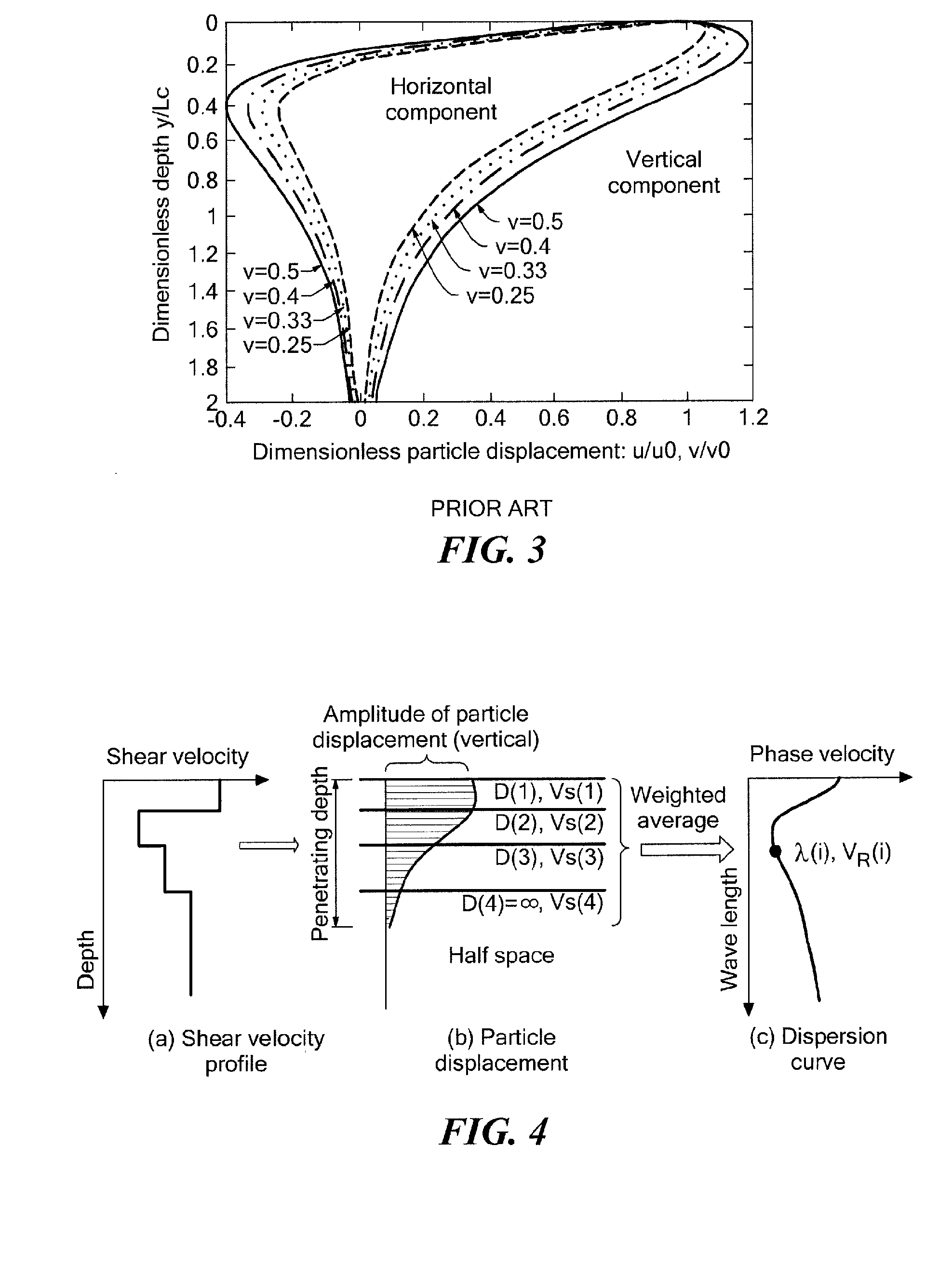
The patent proposes an innovative inversion algorithm for surface wave processing that utilizes the characteristics of surface waves. The algorithm is based on the relationship between shear velocity and particle displacement distribution. The algorithm requires no manual input or adjustment of trial profiles and is fully automated. It is faster and more efficient than existing methods and does not require a forward analysis of the stiffness matrix.

Problems solved by technology

Since no forward analysis to the stiffness matrix is needed, either, this method is extremely fast.

Method used


Image

  • Real-time pavement profile sensing system using air-coupled surface wave
  • Real-time pavement profile sensing system using air-coupled surface wave
  • Real-time pavement profile sensing system using air-coupled surface wave

Examples


Embodiment Construction

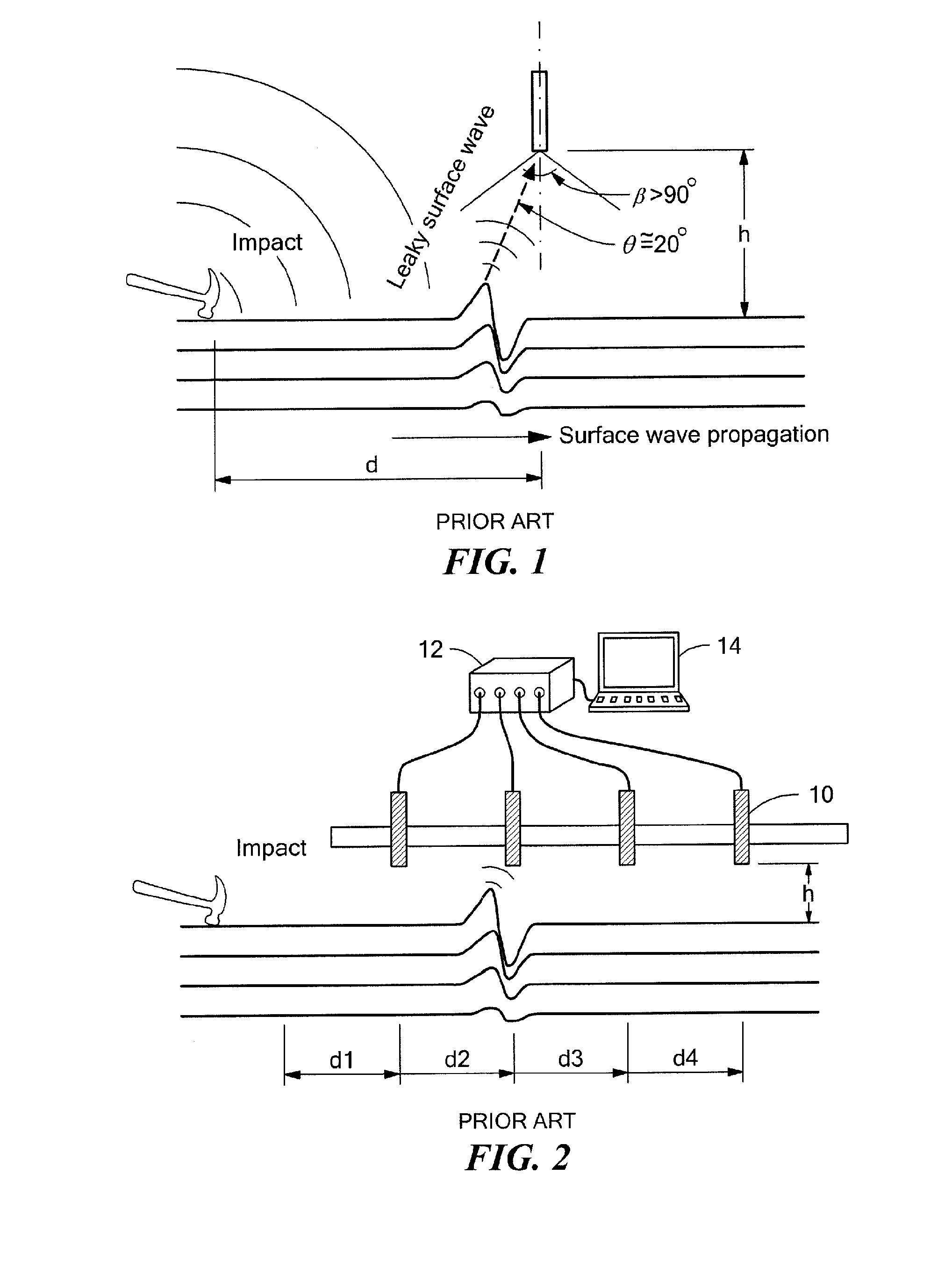
[0026]With regard to a layered pavement structure subject to a point load impact at the surface thereof, a surface wave propagates horizontally in addition to the propagation of P waves (compressional waves) and S waves (shear waves). This is depicted in FIG. 1. Surface vibration resulting from the surface wave propagation acts as an acoustic source and radiates an acoustic wave into the air close to the surface. This radiated acoustic wave is the so-called leaky surface wave. According to Snell's law, the leaky angle θ (relative to the surface normal) is determined by:

sin(θ)=CacR(1)

where, Ca is the acoustic wave velocity in the air and CR is the surface wave (Rayleigh wave) velocity in the pavement. Ca is about 340 m / s, and CR can be 1000 m / s. Therefore, the leaky angle θ≅20°. The leaky surface wave can be detected with a directional microphone 10, which usually has an effective angle of approximately 100°.

[0027]The SASW test has typically been performed using accelerometers applie...


PUM

PropertyMeasurementUnit
effective angleaaaaaaaaaa
time lagaaaaaaaaaa
vertical distanceaaaaaaaaaa

Abstract

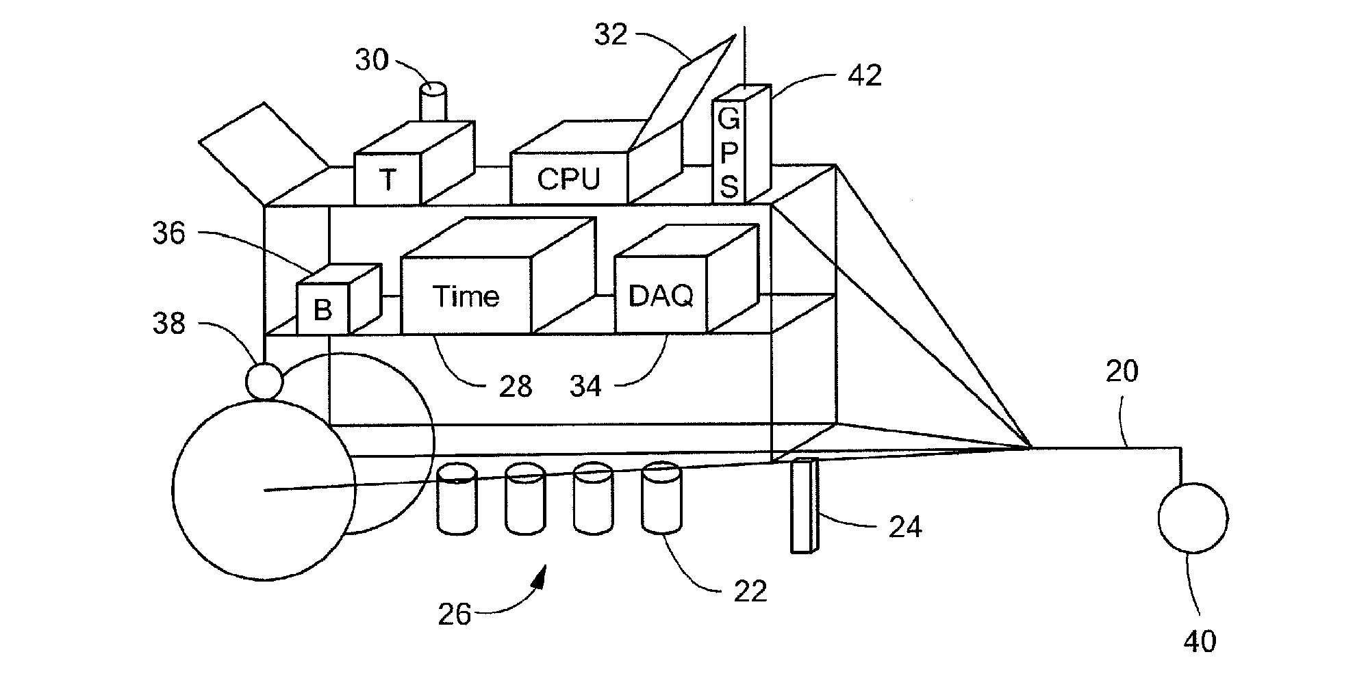
A non-contact testing system and method using acoustic sensors and a mobile sensing system using this system and method is disclosed. The leaky surface wave is recorded with directional microphones. A fast inversion analysis algorithm is introduced to estimate the shear velocity profile and elastic modulus for the subsurface layers of pavement structures, using the dispersion curves obtained from the acoustic signals. An electrical hammer is used to produce impact impulses automatically. A mobile sensing system is integrated on a mobile cart to perform the mobile subsurface sensing for pavement structures.

Description

CROSS REFERENCE TO RELATED APPLICATIONS[0001]This application claims the priority of U.S. Provisional Application No. 61 / 434,522, filed Jan. 20, 2011, entitled, REAL-TIME PAVEMENT PROFILE SENSING SYSTEM (RPPSS) USING AIR-COUPLED SURFACE WAVE. The aforementioned related application is hereby incorporated by reference in its entirety.STATEMENT REGARDING FEDERALLY SPONSORED RESEARCH OR DEVELOPMENT[0002]The research leading to this invention was carried out with U.S. Government support provided under a grant from the National Institute of Standards and Technology (NIST) Technology Innovation Program (TIP), Grant No. 70NANB9H9012. The U.S. Government has certain rights in the invention.BACKGROUND OF THE INVENTION[0003]Highway pavement is typically a layered structure consisting of surface courses, a base, and a sub-base all deposited on the sub-grade. Deterioration of pavement results not only from surface cracks and potholes due to tire friction, but also from de-bonding or stripping of...

Claims


Application Information

Patent Timeline
Patent Type & Authority Applications(United States)
IPC IPC(8): G01N29/11
CPCG01V1/303G01N29/11E01C23/01G01N2291/044
Inventor CAO, YINGHONGWANG, MING
Owner NORTHEASTERN UNIV
Learn More