Method and Apparatus for All Duty Current Sensing in Current Mode Converter

a current mode converter and current sensing technology, applied in the direction of electric variable regulation, process and machine control, instruments, etc., can solve the problems of reducing efficiency or accuracy of converting input voltage vin into output voltage vout, users may have difficulty obtaining the related conduction information of the switch transistor sw,

Active Publication Date: 2013-11-07
ANPEC ELECTRONICS CORPORATION
View PDF5 Cites 66 Cited by
  • Summary
  • Abstract
  • Description
  • Claims
  • Application Information

AI Technical Summary

Problems solved by technology

Therefore, users are unable to utilize the current sensing circuit 108 to immediately respond to related conduction information of the voltage converter apparatus 10, which may influence generation of the pulse width modulation signal to reduce efficiency or accuracy for transforming the input voltage Vin into the output voltage Vout.
The users may have difficulties obtaining the related conduction information of the switch transistor SW2, such as a slope change of the conduction current passing through the switch transistor SW2.
Therefore, it has become an important issue to provide an adaptive current measurement module for the voltage converter apparatus to improve efficiency / accuracy of transforming the input voltage into the output voltage.

Method used


Image

  • Method and Apparatus for All Duty Current Sensing in Current Mode Converter
  • Method and Apparatus for All Duty Current Sensing in Current Mode Converter
  • Method and Apparatus for All Duty Current Sensing in Current Mode Converter

Examples


Embodiment Construction

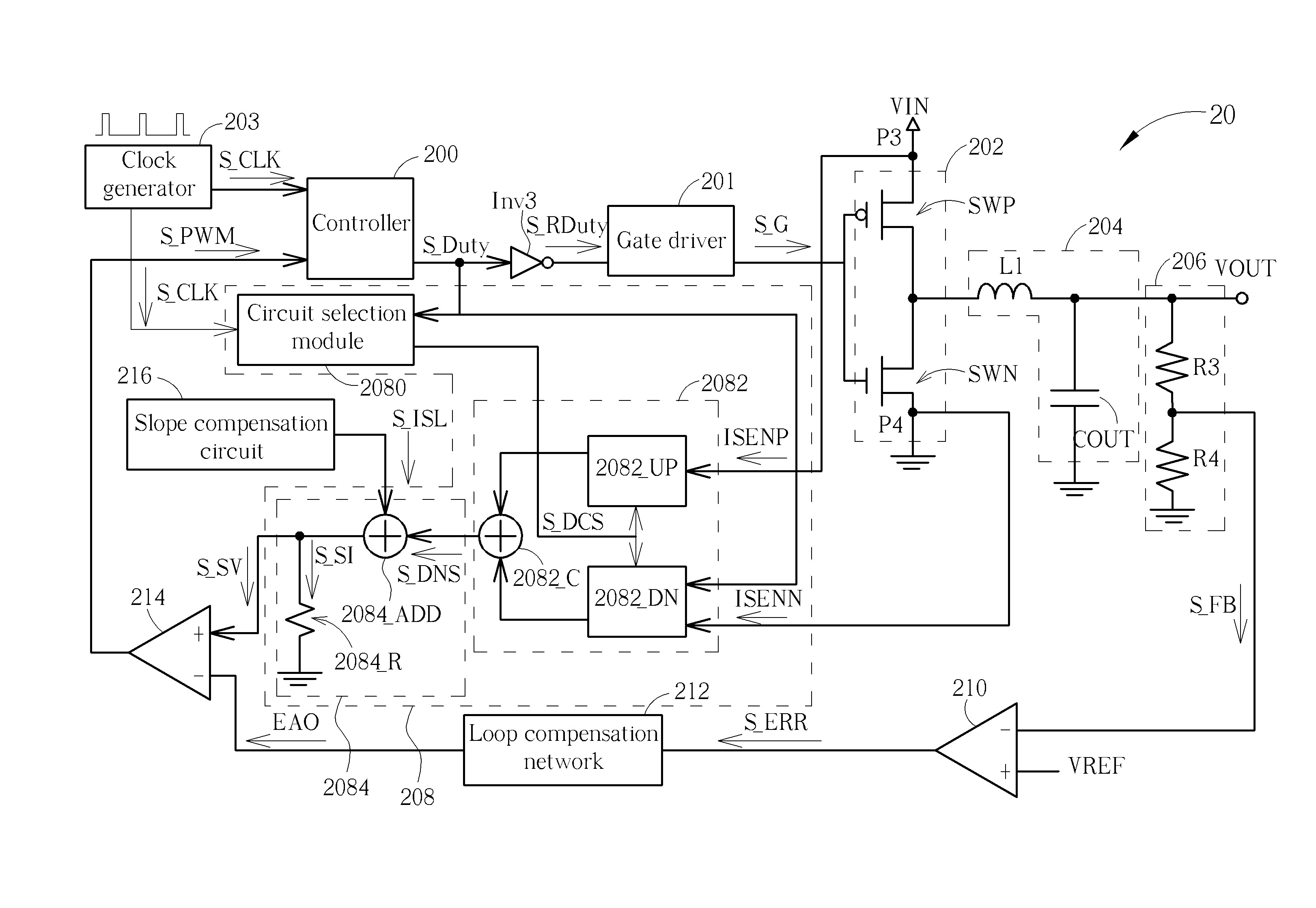
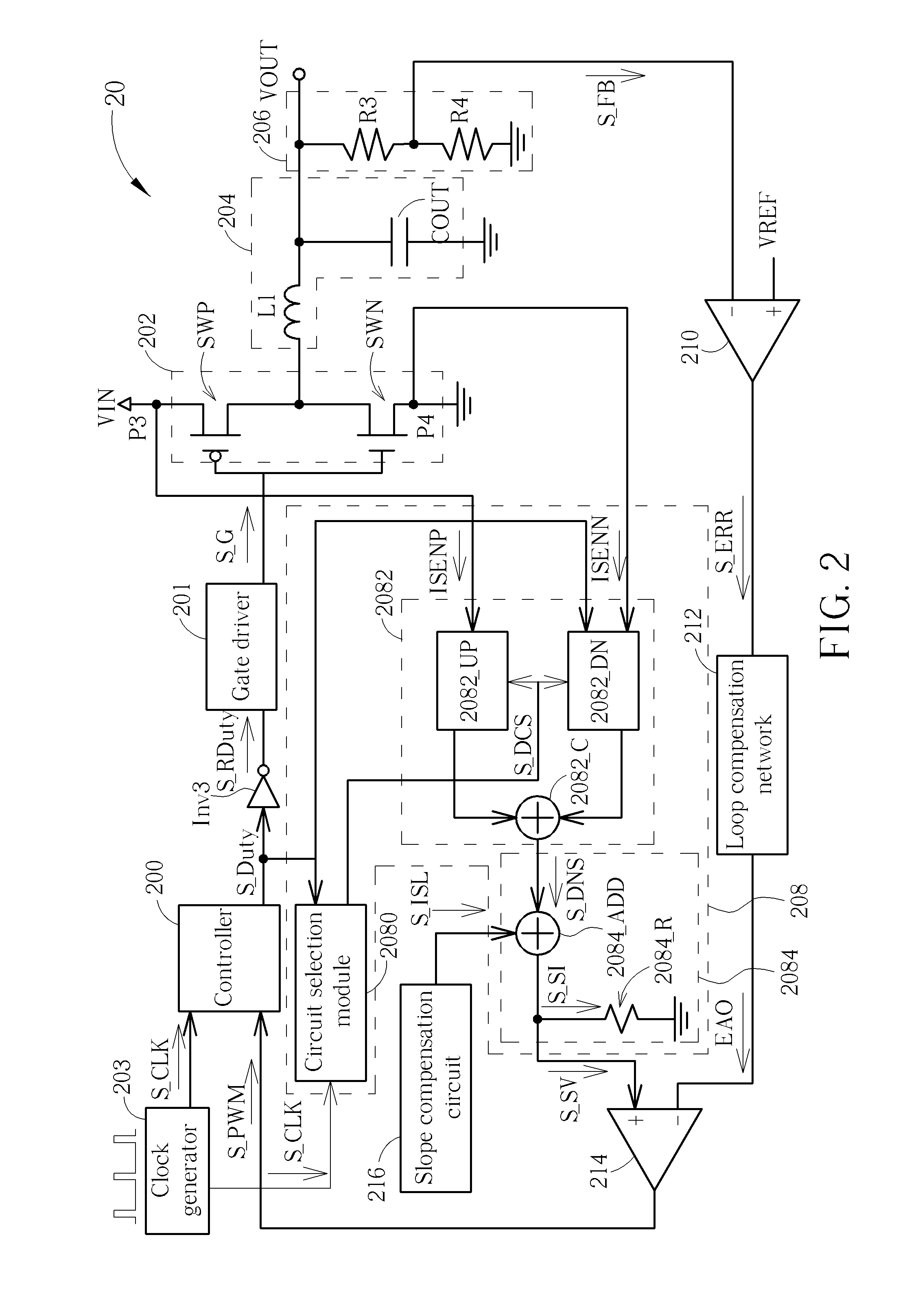
[0028]Please refer to FIG. 2, which illustrates a schematic diagram of a voltage converter apparatus 20 according to an embodiment of the invention. As shown in FIG. 2, the voltage converter apparatus 20 includes a controller 200, a gate driver 201, a driver circuit 202, a clock generator 203, an output circuit 204, a feedback circuit 206, a current sensing circuit 208, an error amplifier 210, a loop compensation network 212, a pulse width modulation comparator 214 and a slope compensation circuit 216. To compare FIG. 1 with FIG. 2, the voltage converter apparatus 20 is similar to the voltage converter apparatus 10, and further includes the current sensing module 208 including a circuit selection module 2080, a current sensing module 2082 and a current generation module 2084 to simultaneously measure conduction currents of an up-bridge circuit and a down-bridge circuit.

[0029]From the element connection, the controller 200 is coupled to the gate driver 201 via an inverter Inv3. Also,...


PUM


Abstract

A current sensing apparatus for a voltage converter apparatus includes a circuit selection module for generating a circuit selection result according to a clock signal and a duty cycle signal; a current sensing module coupled to the circuit selection module, an up-bridge circuit and a down-bridge circuit of the voltage converter apparatus for measuring an up-bridge conduction current and a down-bridge conduction current according to the circuit selection result; and a current generation module coupled to the current sensing module and a slope compensation circuit of the voltage converter apparatus for generating a sensing voltage according to a slope compensation current, the up-bridge conduction current or the down-bridge conduction current, so as to adjust the duty cycle signal of the controller. The current sensing apparatus utilizes the duty cycle signal to drive the voltage converter apparatus.

Description

BACKGROUND OF THE INVENTION[0001]1. Field of the Invention[0002]The present invention relates to a current sensing apparatus and a voltage converter apparatus, and more particularly, to a current sensing apparatus and a voltage converter apparatus which can simultaneously measure conduction currents of an up-bridge circuit and a down-bridge circuit.[0003]2. Description of the Prior Art[0004]Electronic devices usually have different composing elements that operate with different operational voltages. Thus, it is necessary to utilize different DC-DC voltage converters in order to achieve different voltage modulations, such as modulation for raising voltage values or degradation voltage values, and to maintain them at predetermined voltage values. Many types of DC-DC voltage converters have been widely developed and are derived from the buck / step down converter or the boost / step up converter. The buck converter can decrease an input DC voltage to a default voltage level, and the boost ...

Claims


Application Information

Patent Timeline
Patent Type & Authority Applications(United States)
IPC IPC(8): G05F1/46
CPCH02M3/1588H02M1/0009Y02B70/10
Inventor CHEN, CHIH-NING
Owner ANPEC ELECTRONICS CORPORATION
Why Eureka
Try Eureka