Multicore optical fiber (variants)

Active Publication Date: 2013-11-07
FIBER OPTICS RES CENT OF THE RUSN ACAD OF SCI FORC
View PDF2 Cites 31 Cited by
  • Summary
  • Abstract
  • Description
  • Claims
  • Application Information

AI Technical Summary

Benefits of technology

[0010]Furthermore, the presence of the barrier layer will reduce the bending optical

Problems solved by technology

However, constantly emerging new applications (e.g. HDTV) dramatically (almost exponentially) increase the requirements to the amount of data to be transmitted.
However underground pipes containing optical fibers, especially in large cities, can hold only a limited number of fibers (diameter of pipes between wells), which prevents increasing the number of optical fibers laid in them.
The main problem in designing multicore fibers is the optical cross-talk, i.e. the interference of the signals carried in one core with the signals carried in other cores.
The disadvantage of this approach is the big distance between the cores, which allows placin

Method used


Image

  • Multicore optical fiber (variants)
  • Multicore optical fiber (variants)
  • Multicore optical fiber (variants)

Examples


Embodiment Construction

[0054]A multicore fiber will be described with reference to FIGS. 1a-b and 2.

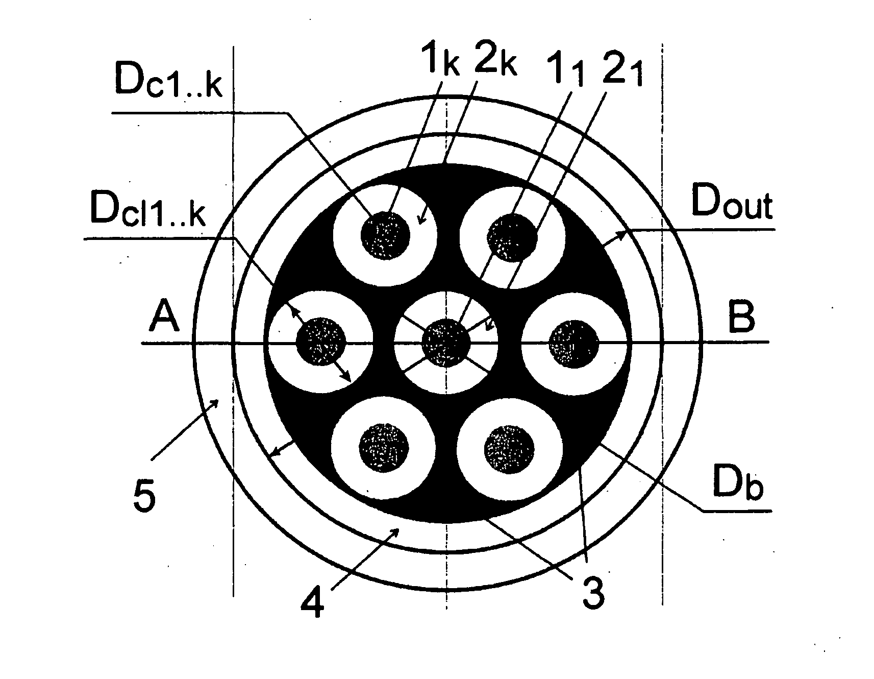
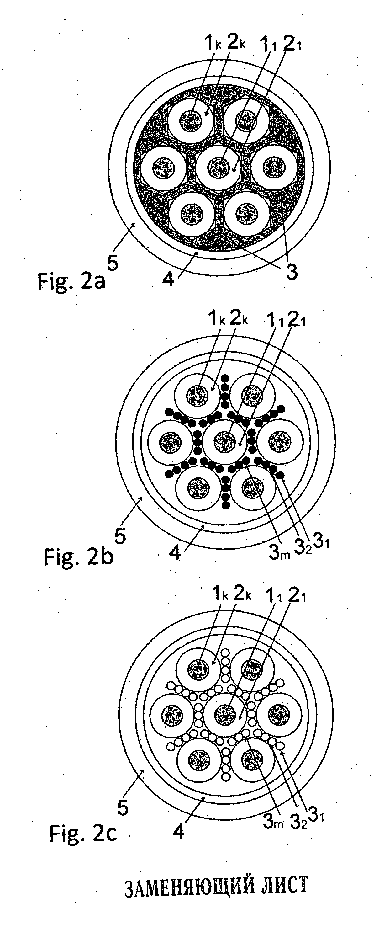
[0055]FIG. 1 shows a multicore optical fiber comprising at least two light-guiding cores (11 . . . 1k), each of the cores being surrounded by a respective inner reflecting cladding (21 . . . 2k), a barrier region (3), which is defined by the space between the inner reflecting claddings (21 . . . 2k) and an outer cladding (4), as well as an external protective coating (5) of the multicore fiber. The external protective coating (5) is used to prevent mechanical damage to the fiber in operation.

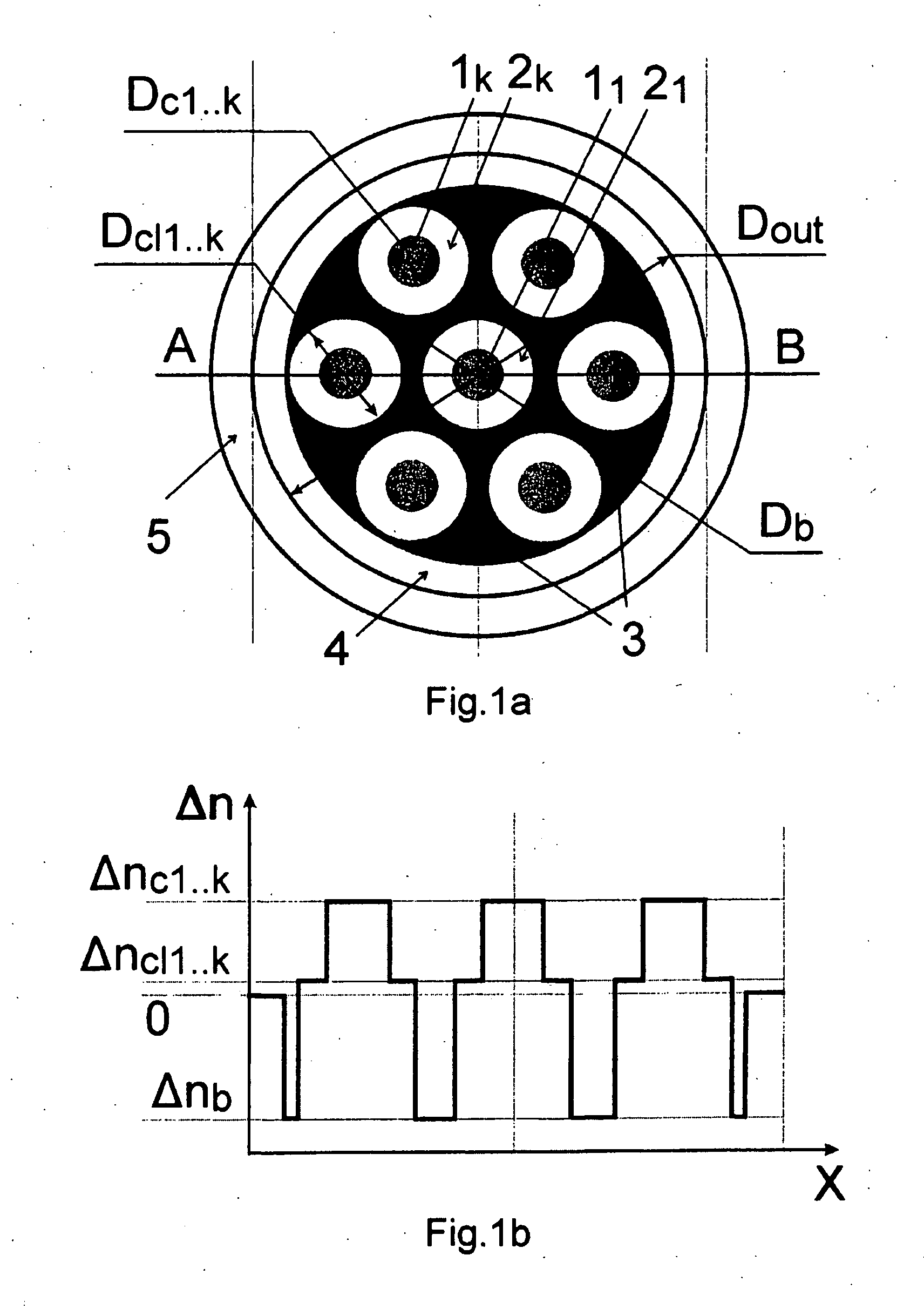
[0056]FIG. 1b shows an exemplary refractive index profile of a multicore fiber according to the invention, where

[0057]Δnc1 . . . k is the difference in the refractive index of each of the light-guiding cores (11 . . . 1k) relative to refractive index no of the outer cladding (4);

[0058]Δncl1 . . . k is the difference in the refractive index of each of said inner reflecting claddings (21 . . . 2k) relative to refractive i...


PUM


Abstract

The invention relates to optical fiber communications. A multicore optical fiber comprises at least two light-guiding cores made of doped fused silica with refractive indices nc1, nc2, nck, each light-guiding core of the at least two light-guiding cores being surrounded by a respective arbitrarily shaped inner reflecting cladding made of fused silica or doped fused silica with refractive indices nc11, nc12, nclk, which are less than the refractive indices nc1, nc2, nck of respective light-guiding cores; a continuous or intermittent barrier region made of fused silica and having an arbitrary cross-sectional shape, the barrier region being formed in the space between the inner reflecting claddings and an outer cladding of fused silica with refractive index n0, the barrier region having refractive index nb, which is less than the refractive index of each of the inner reflecting claddings; and an external protective coating. In another embodiment the barrier region can be formed of through holes in fused silica or doped fused silica.

Description

FIELD OF THE INVENTION[0001]The present invention relates to fiber optics, and more particularly to optical fibers with multiple cores for fiber-optic communication lines.[0002]The invention is applicable in optical communications systems as a transmitting fiber utilized to deliver signal in intracity communication lines when the number or general section of the laid fiber-optic cables is limited.BACKGROUND OF THE INVENTION[0003]For signal transmission in optical communication lines, standard single-mode optical fibers having a single light-guiding core are used. Modern telecommunications optical fibers are capable of long-range transmission of huge amounts of data. However, constantly emerging new applications (e.g. HDTV) dramatically (almost exponentially) increase the requirements to the amount of data to be transmitted. To maintain a high data transfer rate all the way to the end user and reduce power consumption, it is necessary to minimize converting the optical signals to ele...

Claims


Application Information

Patent Timeline
IPC IPC(8): G02B6/02
CPCG02B6/02042G02B6/02395G02B6/036
Inventor DIANOV, EVGENY MIKHAILOVICHSEMENOV, SERGEI LVOVICHEGOROVA, OLGA NIKOLAEVNA
Owner FIBER OPTICS RES CENT OF THE RUSN ACAD OF SCI FORC
Why Eureka
Try Eureka