Ceramic material for high temperature service

a ceramic material and high temperature technology, applied in the direction of blade accessories, machines/engines, textiles and paper, etc., can solve the problems of greater than the bond strength, the structure formed upon coating manufacture changes, and the thermal barrier cannot function, so as to achieve a greater effect on performan

Active Publication Date: 2013-11-07
SULZER METCO (US) INC
View PDF10 Cites 14 Cited by
  • Summary
  • Abstract
  • Description
  • Claims
  • Application Information

AI Technical Summary

Benefits of technology

[0018]Conventional approaches to improving coating life-cycles have focused on adding stabilizers to the base ceramic material. The approach of the present invention provides previously unexpected results in sintering data by identifying low-impurity materials. When looking at the sintering data, changing the amount of impurities slightly has a much greater effect on performance compared with changing the amount and types of stabilizers.

Problems solved by technology

If there were no cracks in the coating, the thermal barrier would not function, because the differences in thermal expansion between the metal substrate system and the coating will cause interfacial stresses upon thermal cycling that are greater than the bond strength between them.
In addition to this, cracks are also formed during service, so the structure formed upon coating manufacture changes with time, depending on the starting material phases in the manufactured coating and thermal conditions during service.
When the coating is cycled above half of its absolute melting temperature, the coating begins to sinter causing volume shrinkage.
Hafnia may also be employed due to its chemical similarity to zirconia, but is generally cost-prohibitive.
Hafnia also is typically present in most zirconia materials in more than trace amounts due to difficulty in separating the two oxides.
Zirconia alone cannot fulfill the coating requirements because it undergoes a phase transformation from tetragonal to monoclinic during thermal cycling.
This transformation is presumed to cause a detrimental volume change resulting in large strain differences between the coating and the substrate.
These coatings have low structural integrity so they are readily abraded when they come into contact with a moving surface with higher structural integrity (such as the blade of a turbine).
However, the heat cycle of in service parts also causes cracks throughout the service life of the part.

Method used


Image

  • Ceramic material for high temperature service
  • Ceramic material for high temperature service
  • Ceramic material for high temperature service

Examples


Embodiment Construction

[0031]Reference will now be made in detail to the preferred embodiments of the invention, examples of which are illustrated in the accompanying drawings.

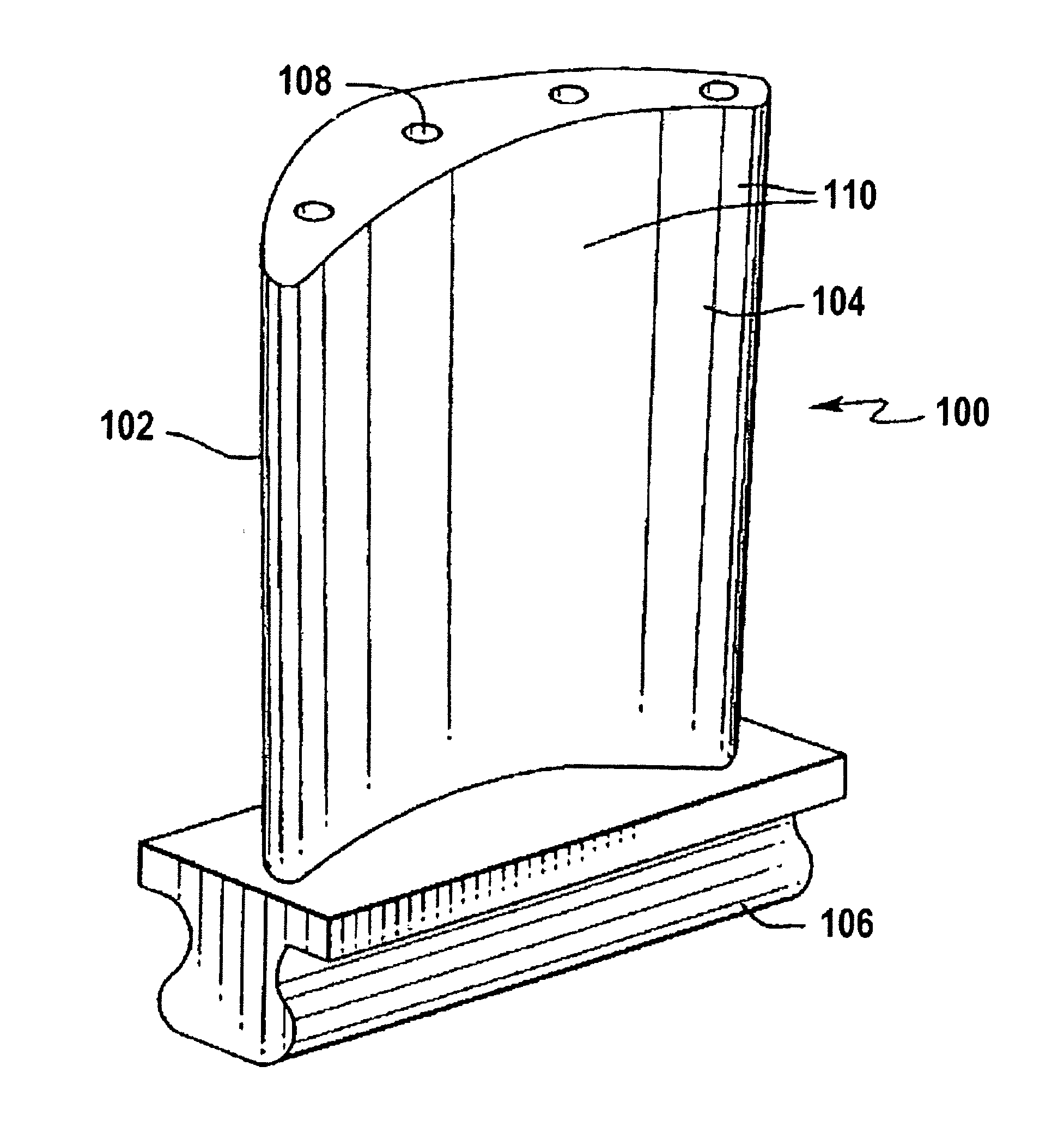
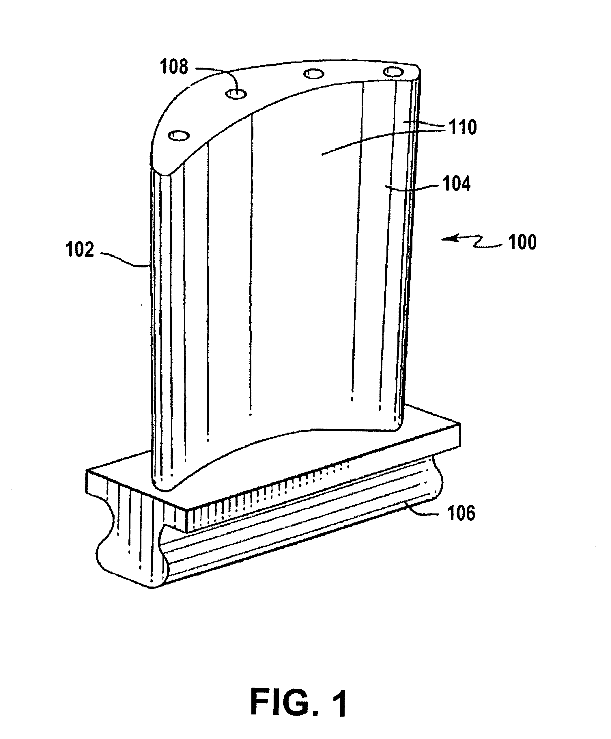
[0032]In an exemplary use of a material of the invention, FIG. 1 shows one component of a turbine. Turbine blade 100 has a leading edge 102 and an airfoil section 104, against which hot combustion gases are directed during operation of the turbine, and which undergoes severe thermal stresses, oxidation and corrosion. A root end 106 of the blade anchors the blade 100. Venting passages 108 may be included through the blade 100 to allow cooling air to transfer heat from the blade 100. The blade 100 can be made from a high temperature resistant material. The surface of the blade 100 is coated with a thermal barrier coating 110 made of ultra-pure zirconia (ZrO2) and / or hafnia (HfO2) alloys in accordance with the invention. The thermal barrier coating 110 may be applied on, for example, a MCrAlY bonding layer with an alumina scale (not sh...


PUM

PropertyMeasurementUnit
lengthaaaaaaaaaa
particle sizeaaaaaaaaaa
weight percentaaaaaaaaaa

Abstract

Thermal barrier coating made from a thermally sprayable powder that includes yttria stabilized zirconia and hafnia, from 6 to 9 weight percent yttria, and total impurities less than or equal to about 0.1 weight percent. The thermal barrier coating has from about 5 to 250 vertical macro cracks per 25.4 mm length measured along a coating surface and the macro cracks are oriented perpendicular to a surface of a substrate containing said coating.

Description

CROSS REFERENCE TO RELATED APPLICATIONS[0001]The present application is a continuation of parent U.S. application Ser. No. 11 / 790,430 filed on Apr. 25, 2007, which parent application is a continuation-in-part of U.S. patent application Ser. No. 11 / 520,043, filed Sep. 13, 2006, which application claims the benefit under 35 U.S.C. §119(e) of U.S. Provisional Patent Application No. 60 / 724,268, filed on Oct. 7, 2005. The entire disclosure of each of the herein listed applications is incorporated herein by reference.STATEMENT REGARDING SPONSORED RESEARCH OR DEVELOPMENT[0002]Not Applicable.REFERENCE TO SEQUENCE LISTING[0003]Not Applicable.BACKGROUND OF THE INVENTION[0004]1. Field of the Invention[0005]The invention relates to ceramic materials for thermal barriers and abradable coating systems in high temperature and high temperature cycling applications, and more particularly to ultra-pure zirconia materials for use in thermal barrier and abradable coating applications.[0006]2. Descripti...

Claims


Application Information

Patent Timeline
Patent Type & Authority Applications(United States)
IPC IPC(8): C04B35/482C09D1/00
CPCC04B35/482C09D1/00C04B35/486C04B35/62665C04B2235/3224C04B2235/3225C04B2235/3227C04B2235/3246C04B2235/72C23C14/083C23C30/00C23C4/11F01D5/288Y02E20/16Y10T428/24273Y10T428/24331Y10T428/24471
Inventor DOESBURG, JACOBUS C.DORFMAN, MITCHELLGOLD, MATTHEWXIE, LIANGDE
Owner SULZER METCO (US) INC
Why Eureka
Try Eureka