
Fail safe damage resistant battery matrix

a battery matrix and damage-resistant technology, applied in the field of multi-cell battery systems, can solve the problems of sudden high current discharge, integrated communications and/or weapons gear utilization, and battery systems becoming an increasing threat to users

Active Publication Date: 2013-11-07
INT COMPONENTS
View PDF5 Cites 24 Cited by
  • Summary
  • Abstract
  • Description
  • Claims
  • Application Information

AI Technical Summary

Benefits of technology

The patent describes a battery matrix made up of multiple battery cells that are interconnected using trace grids. The cells are placed on a flexible substrate and can be folded onto each other to reduce the size of the battery matrix. The flexible substrate can also be supported by bend radius support rods to further improve mechanical linkage between the cells. The battery cells can be coupled in series or parallel to increase the overall voltage and fail-safe survivability of the battery matrix. The battery matrix is also encapsulated in a strong jacket for increased durability and flexibility. The technical effects of this design include improved reliability, durability, and flexibility of the battery matrix.

Problems solved by technology

As electrical power storage capacity is increased, battery systems become an increasing threat to users should the battery system suffer mechanical damage and / or control failure.
Failure modes of battery systems may include sudden high current discharge, extreme heat, fire and / or explosion.
Integrated communications and / or weapons gear utilized, for example, by law enforcement and / or military personnel requires increasingly high levels of power storage carried proximate the users body.
In addition to conventional wear and tear, in extreme situations and / or battle environments these power storage systems may be subject to penetration damage from shrapnel and / or projectiles.
If damaged, the potentially explosive rapid power discharge failure modes of these power storage systems may become a further threat to the user.
However, these solutions may unacceptably increase the weight of the resulting systems, reducing mobility.

Method used


Image

  • Fail safe damage resistant battery matrix
  • Fail safe damage resistant battery matrix
  • Fail safe damage resistant battery matrix

Examples


Embodiment Construction

[0018]Penetration fault testing by the inventors indicates that commonly applied battery cell chemistries, such as lithium cobalt, may be reactive to air and / or humidty upon exposure, for example via battery enclosure penetration and / or breach. In particular it has been discovered that such compounds proximate the anode of the battery cell 1 are highly reactive while compounds of the battery cell 1 proximate the cathode are comparatively non-reactive.

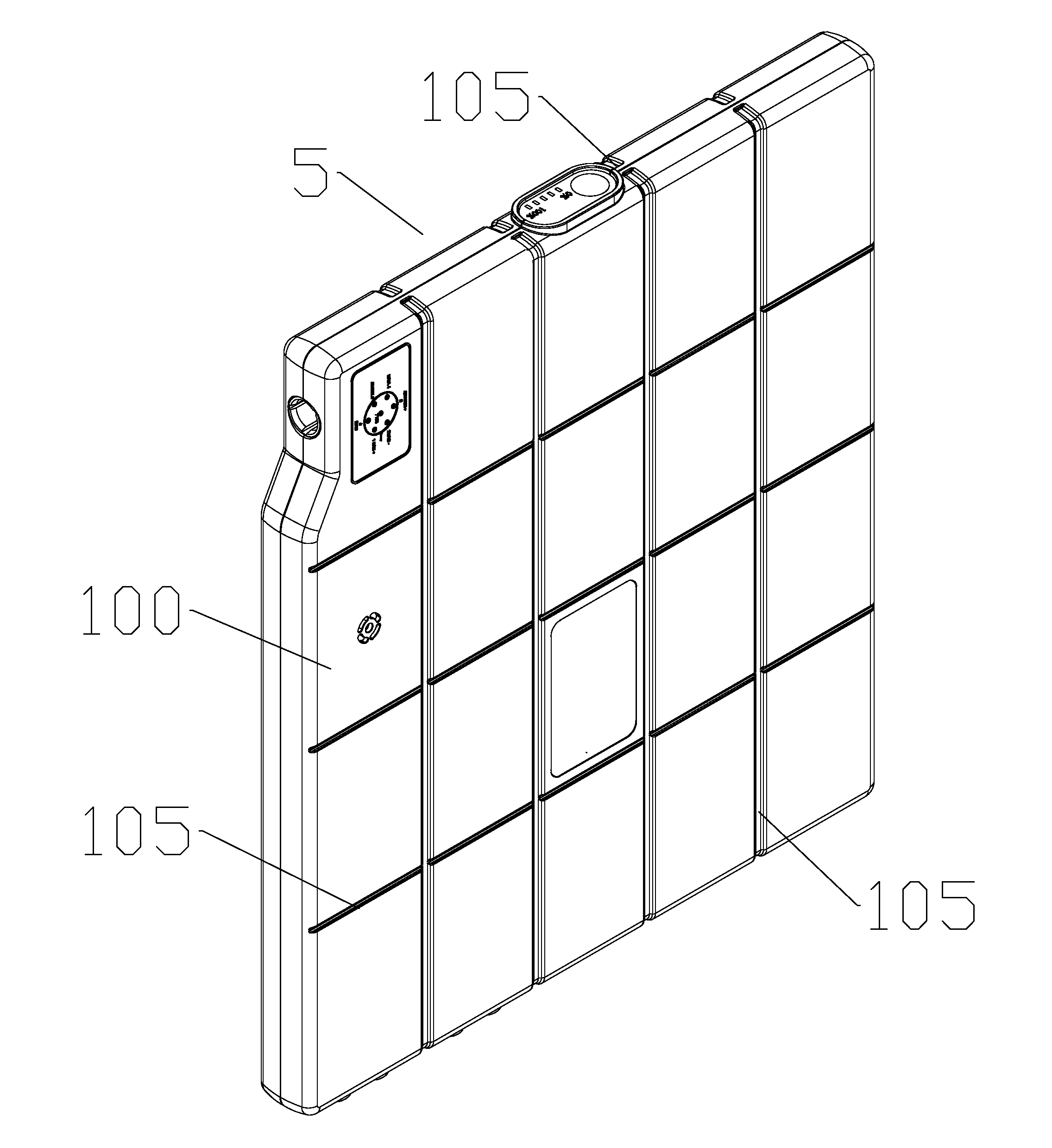
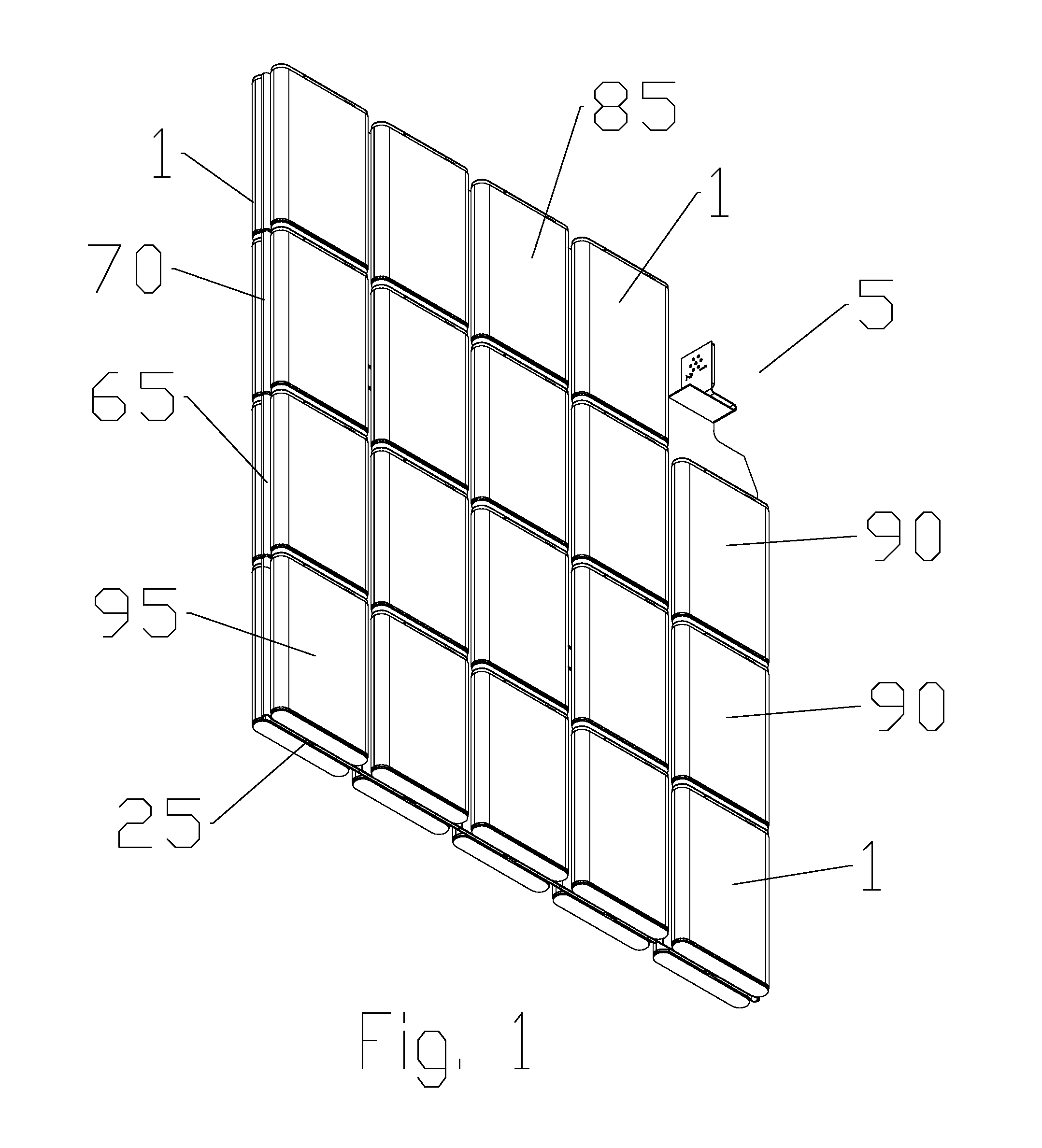
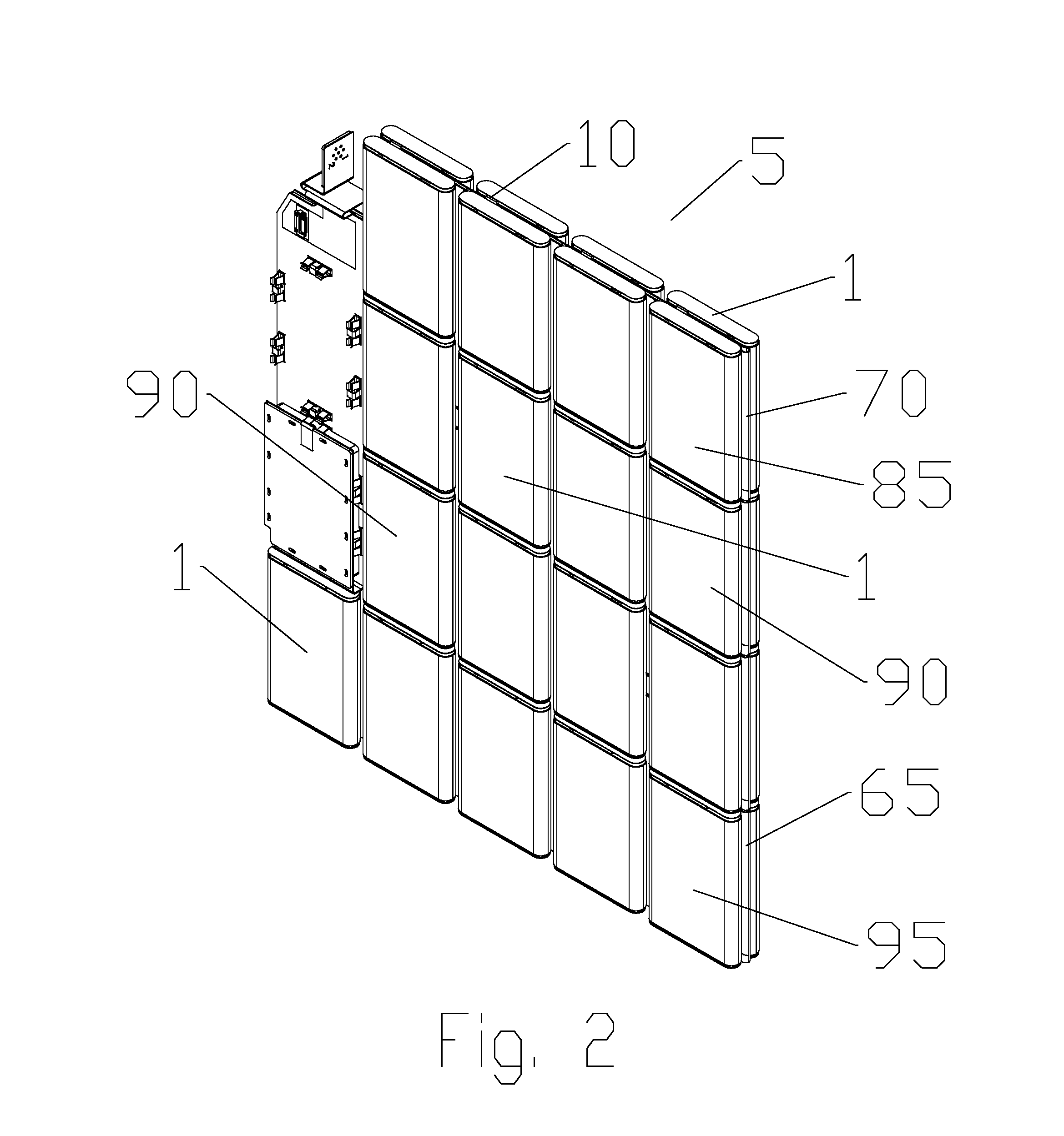
[0019]As shown for example in FIGS. 1 and 2, a battery matrix 5 comprises a plurality of battery cells 1 coupled together to provide electrical power to a desired electrical load. A positive terminal 10 of each battery cell 1 is coupled to a positive trace pad 15 of a positive trace grid 20 and a negative terminal 25 of each battery cell 1 is coupled to a negative trace pad 30 of a negative trace grid 35 (or alternatively the positive and negative terminals may be coupled to an succession of intermediate trace grids 40 as explained here...


PUM

PropertyMeasurementUnit
conductiveaaaaaaaaaa
current capacityaaaaaaaaaa
flexibleaaaaaaaaaa

Abstract

A battery matrix provided with a plurality of battery cells; each of the battery cells provided with a positive terminal and a negative terminal. A positive trace grid and a negative trace grid, each provided as a conductive mesh with an array of apertures forming a plurality of alternative conductive paths across each of the positive and negative trace grids. Each of the battery cells coupled at the positive terminal to a positive trace pad of the positive trace grid and at the negative terminal to a negative trace pad of the negative trace grid. Alternatively, an intermediate trace grid may be introduced so that successive rows of the battery cells are coupled electrically in series with one another.

Description

BACKGROUND[0001]1. Field of the Invention[0002]The invention relates to an electrical power storage system. More specifically, the invention relates to a multiple cell battery system with penetration survivability and fail safe characteristics.[0003]2. Description of Related Art[0004]Battery systems may be utilized to provide mobile and / or remote location electrical power. As electrical power storage capacity is increased, battery systems become an increasing threat to users should the battery system suffer mechanical damage and / or control failure. Failure modes of battery systems may include sudden high current discharge, extreme heat, fire and / or explosion.[0005]Integrated communications and / or weapons gear utilized, for example, by law enforcement and / or military personnel requires increasingly high levels of power storage carried proximate the users body. In addition to conventional wear and tear, in extreme situations and / or battle environments these power storage systems may b...

Claims


Application Information

Patent Timeline
Patent Type & Authority Applications(United States)
IPC IPC(8): H01M2/02H01M2/30H01M50/209H01M50/503H01M50/505H01M50/509
CPCH01M2200/103H01M2200/30Y02E60/10H01M50/209H01M50/509H01M50/505H01M50/503
Inventor AYUB, ILYASHABEGGER, KENNETHUMLES, MATTHEWBATTS, WILLIAM MARKHOPFER, ALBERT
Owner INT COMPONENTS
Learn More