Combustible gas detection device

a gas detection and combustible technology, applied in the direction of instruments, electrochemical generators, transportation hydrogen technology, etc., can solve the problems of reducing the accuracy of detecting gas concentration, and achieve the effect of reducing the overall size of the combustible gas detection device, simplifying the wiring structure, and convenient connection

Active Publication Date: 2013-11-14
NGK SPARK PLUG CO LTD
View PDF1 Cites 6 Cited by
  • Summary
  • Abstract
  • Description
  • Claims
  • Application Information

AI Technical Summary

Benefits of technology

[0030]According to the combustible gas detection device configured as described above, the heat generation resistor and the temperature measurement resistor can be easily connected to an inpu

Problems solved by technology

Therefore, because of this influence, an error is produced between the actual environmental temperature and the environmental temperature determined

Method used


Image

  • Combustible gas detection device
  • Combustible gas detection device
  • Combustible gas detection device

Examples


Embodiment Construction

[0047]Embodiments of the present invention will now be described with reference to the drawings.

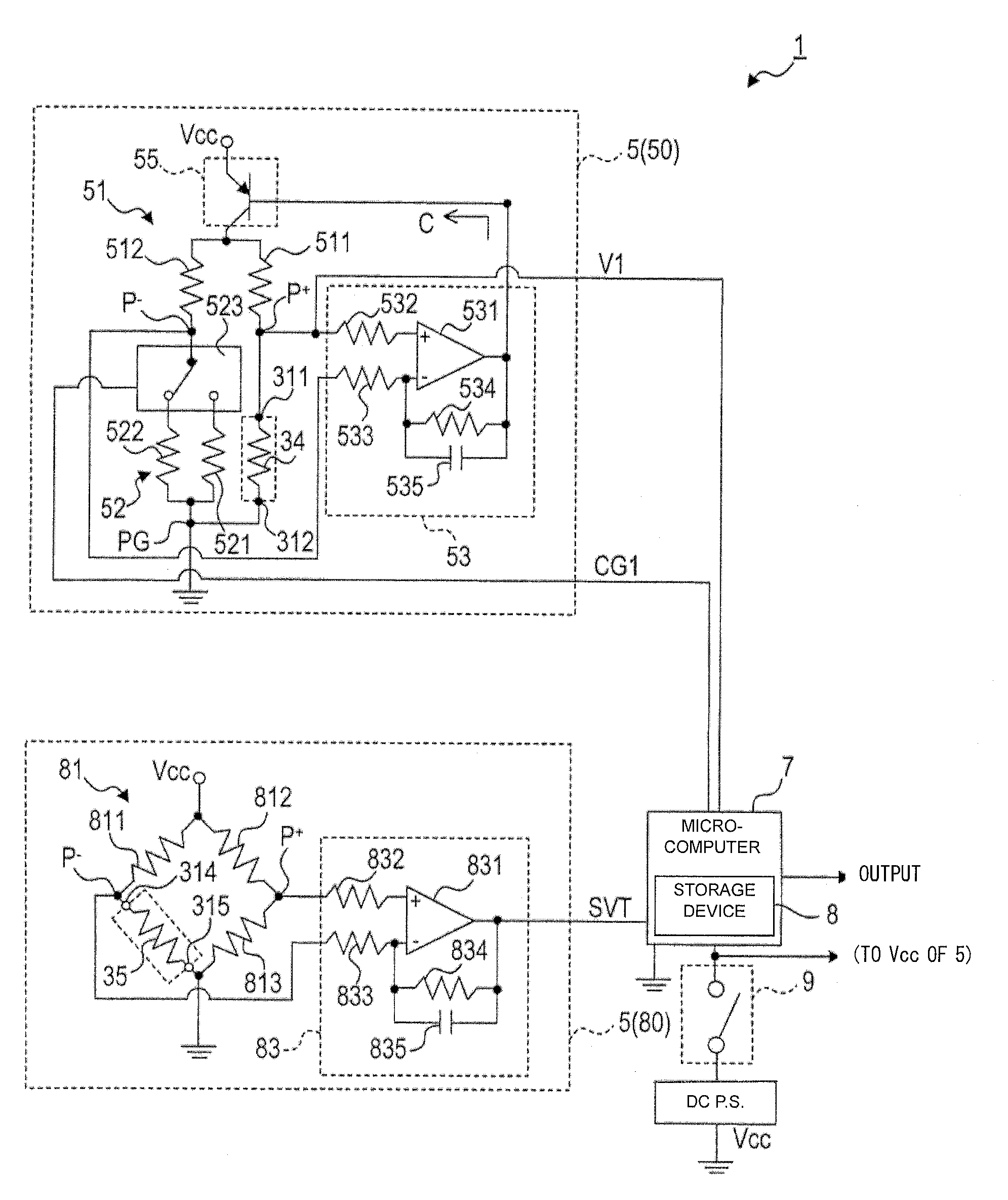
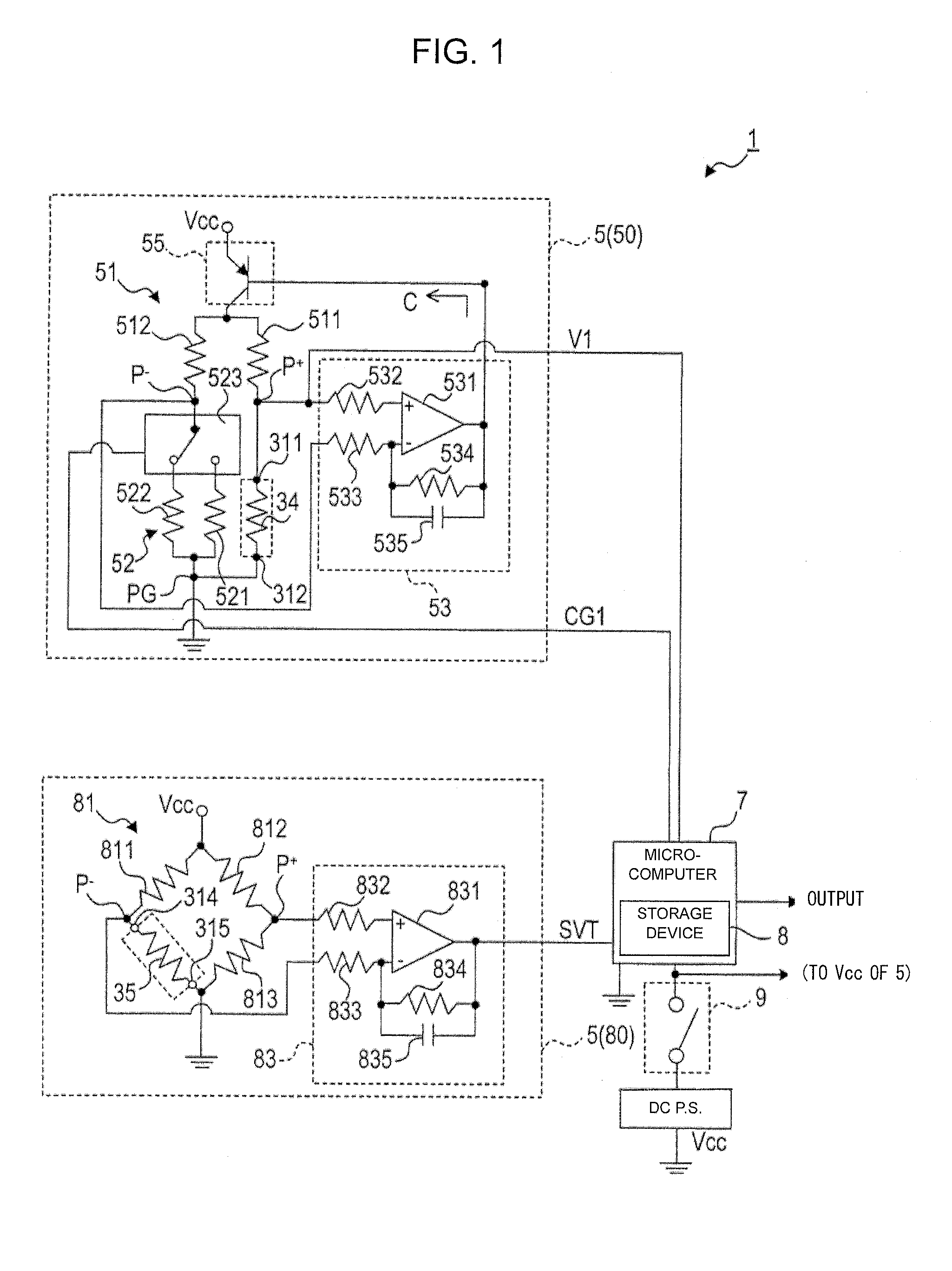
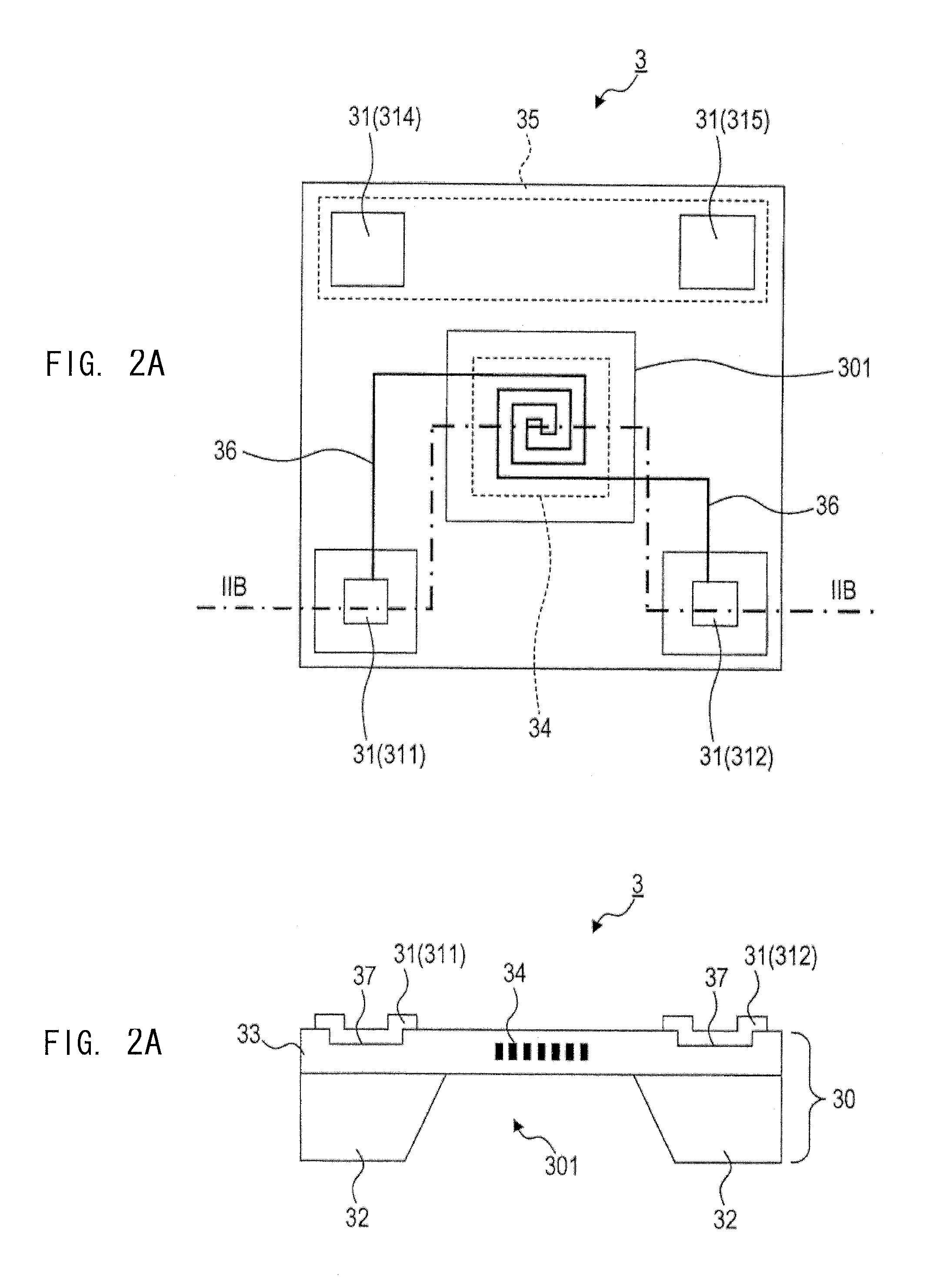
[0048]FIG. 1 is a diagram showing the overall configuration of a combustible gas detection device 1 to which the present invention is applied. FIG. 2A is a plan view showing the structure of a gas detection element 3 which is a main portion of the combustible gas detection device 1 (the view also shows a part of the internal structure), and FIG. 2B is a cross-sectional view of the gas detection element taken along line IIB-IIB in FIG. 2A.

[0049][Overall Configuration]

[0050]The combustible gas detection device 1, which detects the concentration of a combustible gas by using the thermal-conduction-type gas detection element 3, is disposed in, for example, the cabin of a fuel cell automobile for the purpose of, for example, detecting leakage of hydrogen.

[0051]As shown in FIG. 1, the combustible gas detection device 1 includes a control circuit 5 which drives and controls the gas detection ele...


PUM


Abstract

A combustible gas detection device includes an energization control circuit which controls the switching of the energization state of a heat generation resistor every predetermined time period such that the heat generation resistor alternately has resistances corresponding to two predetermined temperatures, a temperature measurement resistor disposed on the same substrate on which the heat generation resistor is disposed, where its resistance changes with the environmental temperature, a gas concentration computation section which calculates the combustible gas concentration by using a voltage generated across the heat generation resistor which is detected when electricity is supplied to the heat generation resistor and the environmental temperature based on a voltage change caused by a change in the resistance of the temperature measurement resistor. The predetermined time period is such that a change in the environmental temperature which occurs when the energization control circuit switches the energization state, falls within a range of 0.5° C.

Description

CROSS-REFERENCE TO RELATED PATENT APPLICATIONS[0001]This application is a U.S. National Phase Application under 35 U.S.C. §371 of International Patent Application No. PCT / JP2012 / 052969, filed Aug. 18, 2011, and claims the benefit of Japanese Patent Application No. 2011-286387, filed on Dec. 27, 2011 and Japanese Patent Application No. 2011-025754 filed on Feb. 9, 2011, all of which are incorporated by reference in their entirety herein. The International Application was published in Japanese on Aug. 16, 2012 as International Publication No. WO / 2012 / 108500 under PCT Article 21(2).FIELD OF THE INVENTION[0002]The present invention relates to a combustible gas detection device which detects the concentration of a combustible gas present in an object atmosphere.BACKGROUND OF THE INVENTION[0003]In recent years, in order to satisfy social needs such as protection of environment and nature, researches have been actively conducted on fuel cells which are efficient and clean energy sources. A...

Claims


Application Information

Patent Timeline
IPC IPC(8): G01N27/18
CPCG01N27/18H01M8/04447H01M2250/20Y02E60/50Y02T90/40G01N25/18
Inventor WATANABE, MASAYAKITANOYA, SHOJIICHIKAWA, DAISUKEYAMASHITA, MASAHIRO
Owner NGK SPARK PLUG CO LTD
Why Eureka
Try Eureka