Electronic cigarette and a wireless charging device for the same

Inactive Publication Date: 2013-11-14
KIMREE HI TECH
5 Cites 49 Cited by

AI-Extracted Technical Summary

Problems solved by technology

Once the battery is out of power, tobacco tars cannot be atomized, thus the electronic cigarette is not available for use.
However, it is not convenient for users to carry the charger or the charging cable along with them when smoking.
Furthermore, they cannot really enjoy the interests of smoking when always bothered by pulling o...

Method used

[0024]Referring to FIG. 4 and FIG. 5, detailed circuit structures of the wireless charging circuit and the electronic cigarette are shown. A receiving coil L2 contributed to the charging process, a rectification diode D7, a capacitor, and a voltage regulator diode ZD4 are added into the circuit of a prior electronic cigarette (which comprises a battery, a control chip U2, a heating wire R, and an atomizer switch S1). The wireless charging device comprises a transmitting control chip U1, an electronic switch Q1, a transmitting coil L1, a compensation capacitor C1 connected in parallel with the tran...

Benefits of technology

[0015]According to the wireless charging device of the present invention, the electronic cigarette can be charged by means of forming a non-contact and inserting structure. Further, the wireless charging device can be used as an inserting sleeve for arranging and placing the electronic cigarette. Compared to those in the prior art, the wireless charging device disclosed by the present invention provides the advantages of: 1) wireless connection and convenient for charging; 2) the wireless charging device is simple in structure and small in volume compar...

Abstract

An electronic cigarette and a wireless charging device for the same. The electronic cigarette comprises a receiving coil electrically connected with a battery. The receiving coil is provided in a body of the electronic cigarette and an axis of the coil is parallel to the electronic cigarette. The charging device comprises an electronic switch and a transmitting coil connected with a power source in sequence. The electronic switch is controlled by a transmitting control unit, and the transmitting coil is used for the electronic cigarette to be inserted therein. A housing of the charging device is provided with an inserting hole or a sleeve, which is placed correspondingly with the transmitting coil. The electronic cigarette and the wireless charging device for the same work in a non-contact manner by using a insert total electromagnetic coupling structure.

Application Domain

Technology Topic

Image

  • Electronic cigarette and a wireless charging device for the same
  • Electronic cigarette and a wireless charging device for the same
  • Electronic cigarette and a wireless charging device for the same

Examples

  • Experimental program(1)

Example

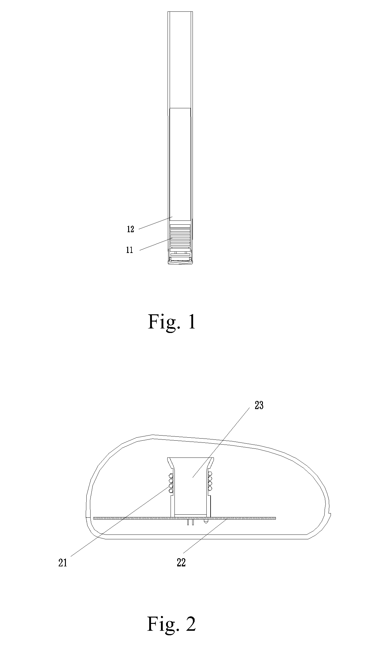
[0021]As shown in FIG. 1, an electronic cigarette according to the present invention is provided, comprising a battery 12 installed on the body of the electronic cigarette, and a receiving coil 11 provided on the head part of the electronic cigarette located in front of the battery 12. The receiving coil 11 is also labeled as L2 in FIG. 3 and FIG. 4.
[0022]As shown in FIG. 2, a wireless charging device for the electronic cigarette according to the present invention is provided, comprising a circuit board 22, a sleeve 23, and a transmitting coil 21. The transmitting coil 21 is also labeled as L1 in FIG. 3 and FIG. 5. The transmitting coil 21 is wrapped outside the sleeve 23, corresponding to the position for inserting the receiving coil 11 of the electronic cigarette. When the electronic cigarette is installed, the receiving coil 11 is inside the transmitting coil 22 with the axes of the two coils in the same direction, thus forming an insert total electromagnetic coupling structure.
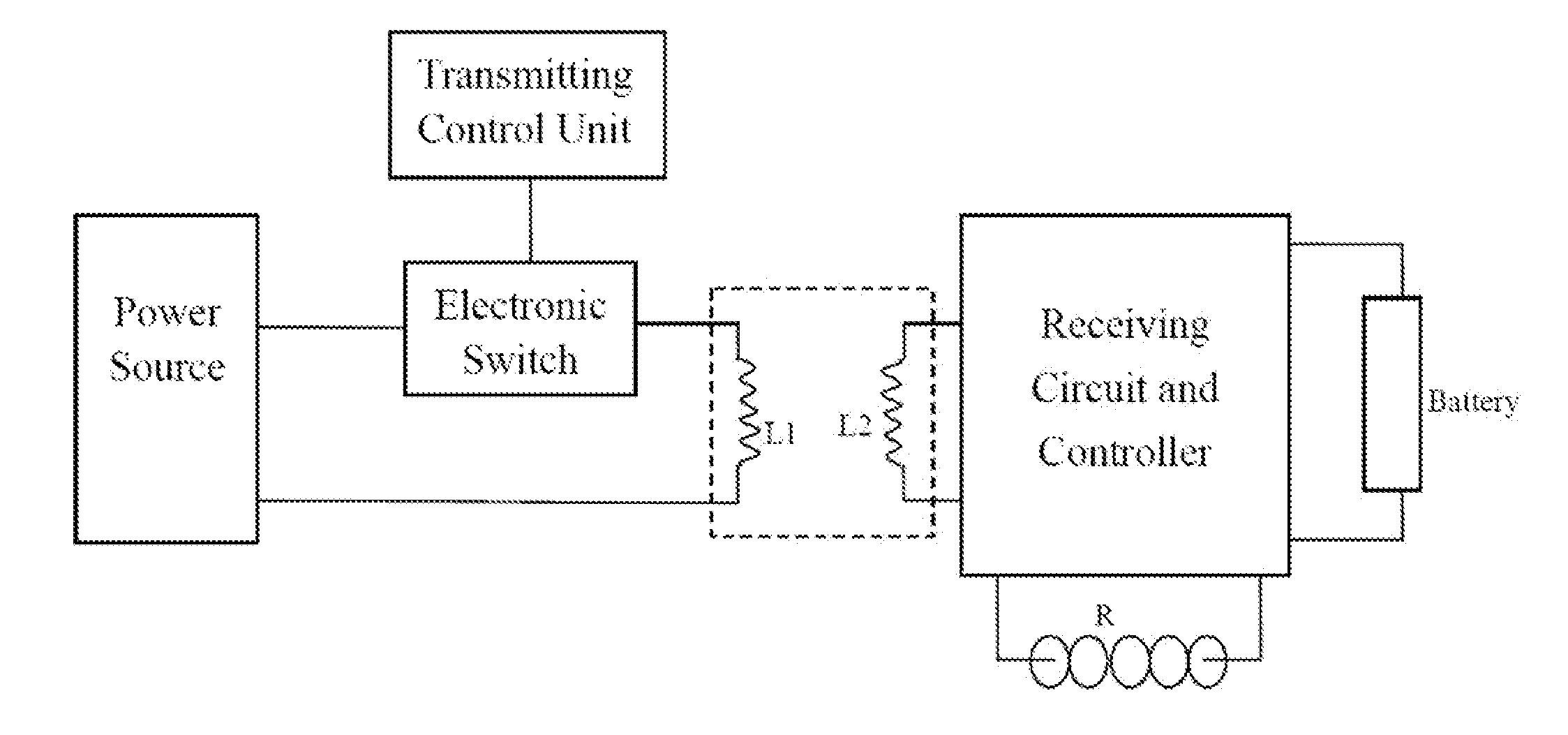
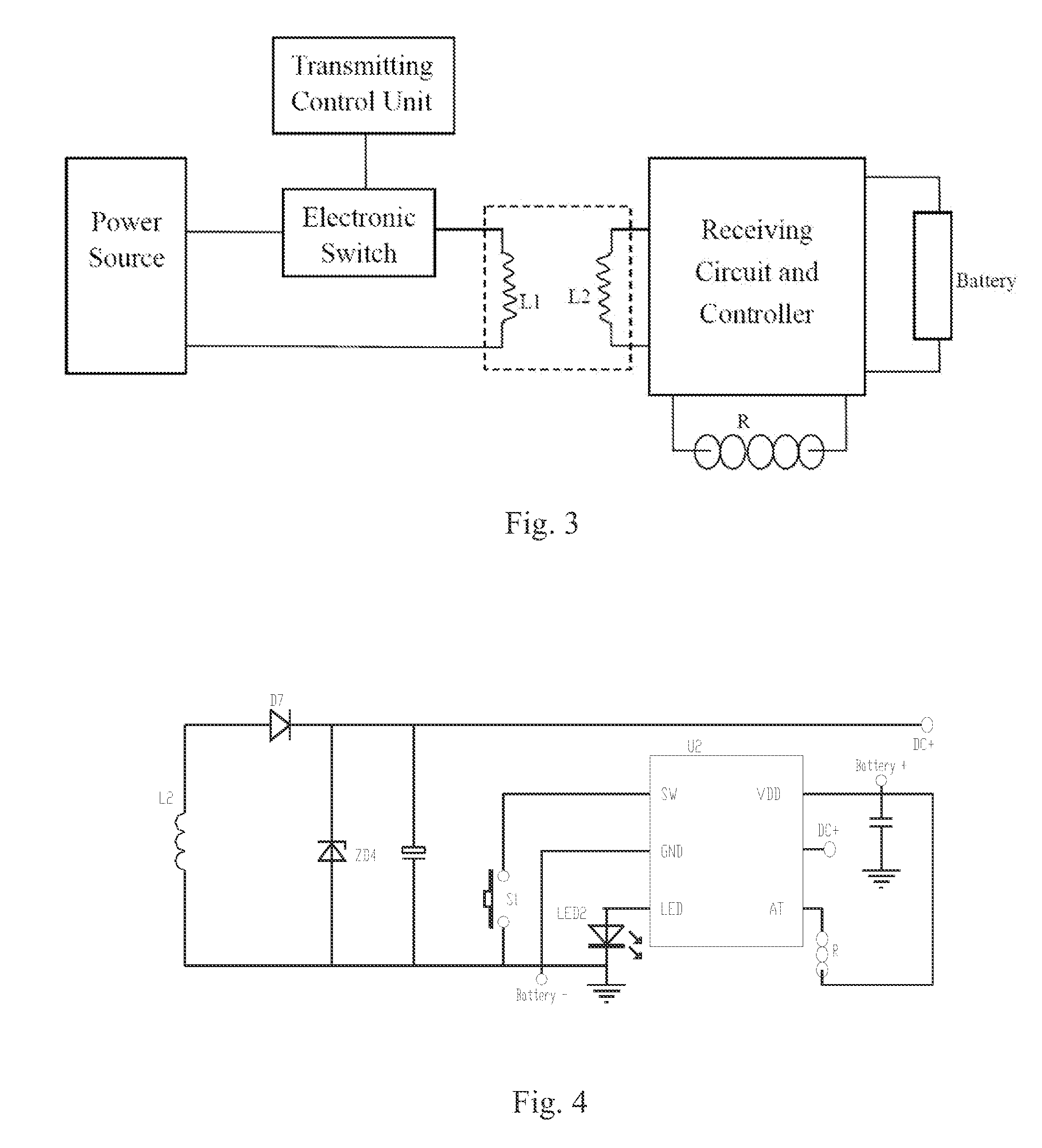
[0023]Referring to FIG. 3, the circuit of the electronic cigarette comprises a battery, a heating wire R, a receiving coil L2, and a receiving circuit and a controller containing a rectification unit. The circuit of the wireless charging device comprises an electronic switch and a transmitting coil L1 electrically connected with a power source in sequence. The electronic switch is provided with a transmitting control unit. The transmitting coil L1 and the receiving coil L2 are configured to cooperate with each other.
[0024]Referring to FIG. 4 and FIG. 5, detailed circuit structures of the wireless charging circuit and the electronic cigarette are shown. A receiving coil L2 contributed to the charging process, a rectification diode D7, a capacitor, and a voltage regulator diode ZD4 are added into the circuit of a prior electronic cigarette (which comprises a battery, a control chip U2, a heating wire R, and an atomizer switch S1). The wireless charging device comprises a transmitting control chip U1, an electronic switch Q1, a transmitting coil L1, a compensation capacitor C1 connected in parallel with the transmitting coil L1 in order to improve the transmitting efficiency, a current limiting resistor R1 connected in serial with the transmitting coil L1 to reduce a current in the transmitting coil L1 and further reduce the amount of heat sinks.
[0025]According to the present invention, the wireless charging device is particularly suitable for electronic cigarette. In that way, the users are able to smoke while charging. Therefore, the electronic cigarettes can be further promoted, and smokers who are suffered from smoking traditional tobaccos can enjoy smoking without harm to their health in a low cost.
[0026]Although explanatory embodiments have been shown and described, it would be appreciated by those skilled in the art that changes, alternatives, and modifications all falling into the scope of the claims and their equivalents may be made in the embodiments without departing from spirit and principles of the present invention.

PUM

no PUM

Description & Claims & Application Information

We can also present the details of the Description, Claims and Application information to help users get a comprehensive understanding of the technical details of the patent, such as background art, summary of invention, brief description of drawings, description of embodiments, and other original content. On the other hand, users can also determine the specific scope of protection of the technology through the list of claims; as well as understand the changes in the life cycle of the technology with the presentation of the patent timeline. Login to view more.

Similar technology patents

Classification and recommendation of technical efficacy words

  • Simple structure
  • Small volume

Microlithographic projection exposure apparatus

InactiveUS20050068499A1Simple structureReliable and low-maintenance operationProjectorsPhotomechanical exposure apparatusCamera lensPhysics
Owner:CARL ZEISS SMT GMBH

Catheter system for protected angioplasty and stenting at a carotid bifurcation

ActiveUS20050197688A1Good curative effectSmall volumeStentsCatheterAngioplasty balloonsCarotid bifurcation
Owner:ENVISION SCI PVT LTD
Why Eureka
Try Eureka