Electronic disc brake

a technology of electronic disc brake and brake disc, which is applied in the direction of fluid actuated brake, gearing, mechanical equipment, etc., can solve the problems that the electronic disc brake may be disadvantageous in terms of operation noise, and achieve the effects of reducing volume, reducing operation noise, and efficient operation

Inactive Publication Date: 2013-11-14
RYU DONG YO +3
View PDF12 Cites 15 Cited by
  • Summary
  • Abstract
  • Description
  • Claims
  • Application Information

AI Technical Summary

Benefits of technology

[0021]Therefore, it is an aspect of the present invention to provide an electronic disc brake which decreases operation noise and is efficiently operated while having a reduced volume, by improving structures of respective components, such as a motor to generate drive force, gears to transmit the drive force, and a reducer to reduce rotational force, and a connection structure between the components.
[0028]The outer gear may be fixed to the motor so as to prevent rotation of the outer gear.

Problems solved by technology

Furthermore, the electronic disc brake may be disadvantageous in terms of operation noise thereof during braking due to the use of the multistage gears.

Method used


Image

  • Electronic disc brake
  • Electronic disc brake
  • Electronic disc brake

Examples


Embodiment Construction

[0043]Reference will now be made in detail to the embodiments of the present invention, examples of which are illustrated in the accompanying drawings, wherein like reference numerals refer to like elements throughout.

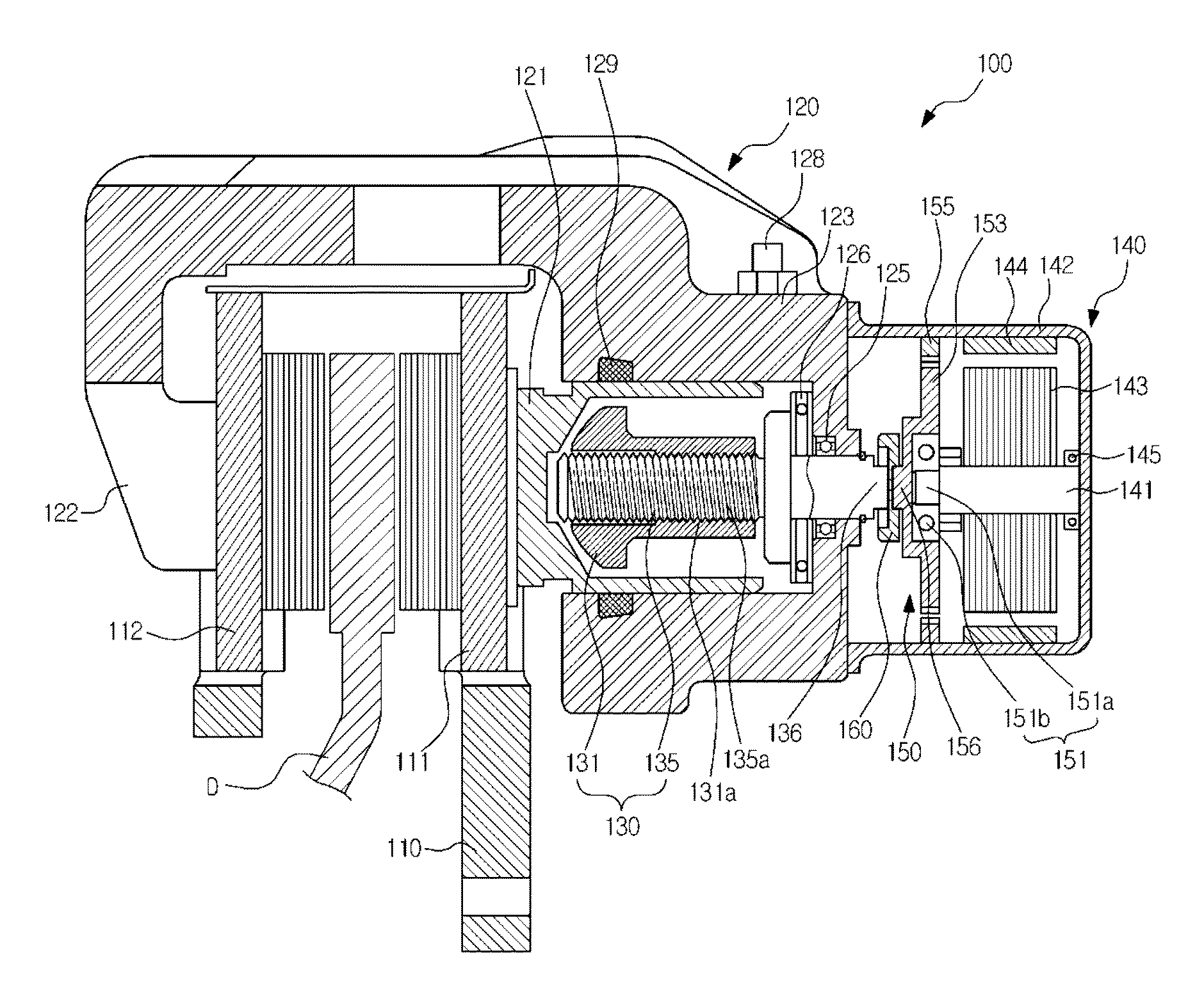
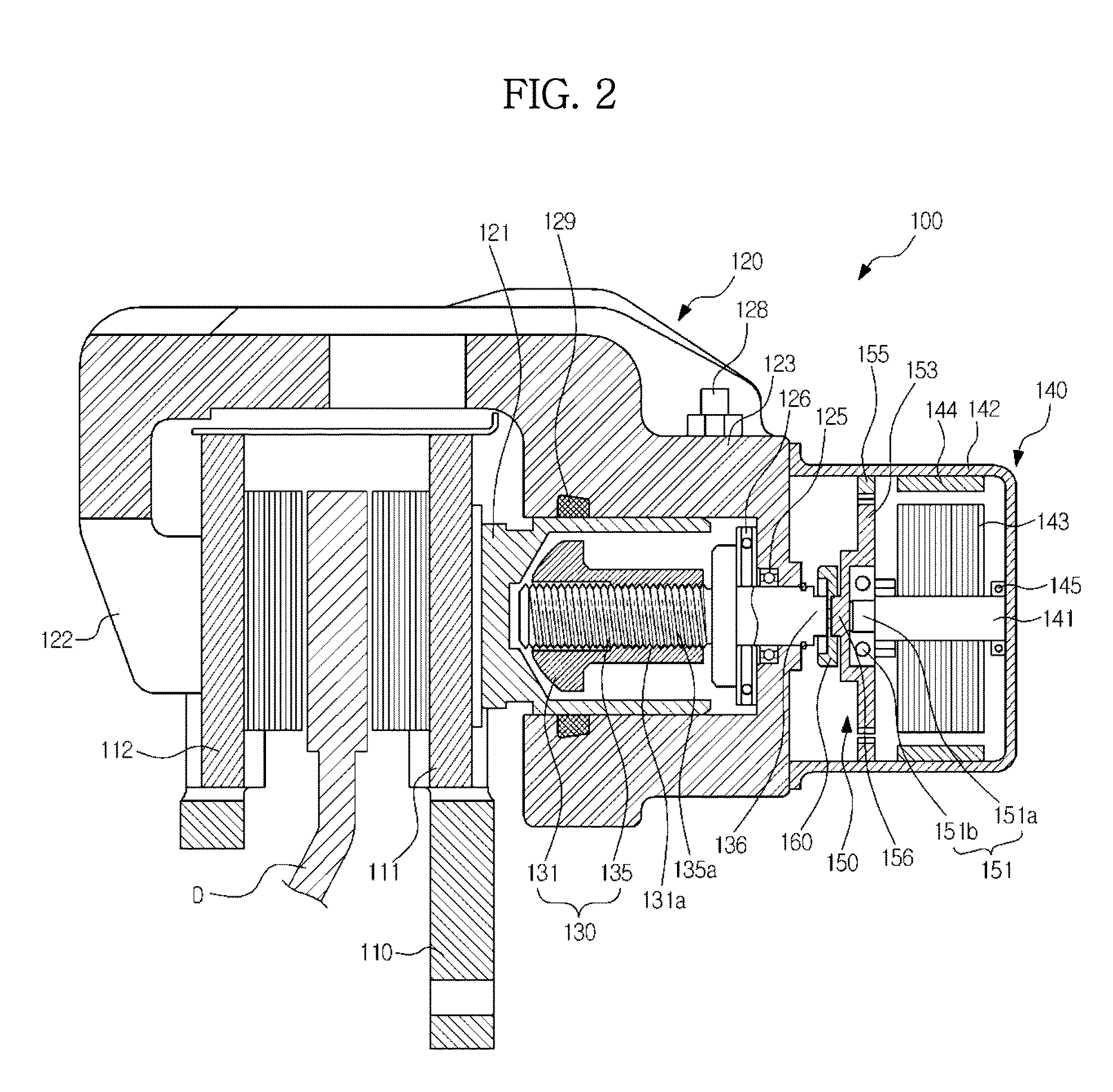
[0044]FIG. 2 is a cross-sectional view schematically illustrating a configuration of an electronic disc brake according to an embodiment of the present invention.

[0045]Referring to FIG. 2, the electronic disc brake 100 includes a disc D which rotates together with a wheel (not shown) of a vehicle, a carrier 110 which is provided with a pair of pad plates 111 and 112 disposed so as to press both side surfaces of the disc D to perform braking, a caliper housing 120 equipped with a piston 121 which is movably mounted therein to press the pair of pad plates 111 and 112, a pressure device 130 which converts rotational force into rectilinear reciprocating motion to press the piston 121, a motor 140 to generate drive force, a reducer 150 connected to the motor 140, and a coup...


PUM


Abstract

Disclosed herein is an electronic disc brake. The electronic disc brake includes a carrier on which a pair of pad plates are mounted, a caliper housing, which is slidably installed on the carrier and is provided with a cylinder having a piston mounted therein, a pressure device installed within the cylinder, the pressure device converting rotational motion into rectilinear motion to press and release the piston, the pressure device having an output key which protrudes by penetrating a rear wall of the caliper housing, a motor mounted on an outer surface of the caliper housing to generate drive force, a reducer coupled with a rotary shaft of the motor to amplify the drive force, and a coupling interposed between the reducer and the pressure device to transmit the amplified drive force to the pressure device, wherein the motor, the reducer, and the pressure device are coaxially connected in series.

Description

CROSS-REFERENCE TO RELATED APPLICATION[0001]This application claims the benefit of Korean Patent Application No. 2012-0049985, filed on May 11, 2012 in the Korean Intellectual Property Office, the disclosure of which is incorporated herein by reference.BACKGROUND[0002]1. Field[0003]Embodiments of the present invention relate to an electronic disc brake capable of simplifying a coupling structure which transmits rotation torque together with drive force of a motor to a gear portion in a serial manner.[0004]2. Description of the Related Art[0005]In general, parking brake devices are devices to stop vehicles so as not to move when the vehicles are parked, and serve to hold wheels of the vehicles so as not to rotate.[0006]Recently, there is used an EPB (electronic parking brake) system to electronically control operation of a parking brake. Such an EPB system is mounted on a typical disc brake and performs a parking brake function. Here, EPB systems are classified into a cable puller ty...

Claims


Application Information

Patent Timeline
Patent Type & Authority Applications(United States)
IPC IPC(8): F16D55/226
CPCF16D55/226F16D65/183F16D2121/24F16D65/095F16D65/18F16H1/34
Inventor RYU, DONG YOYANG, I JINCHOI, SEONG HOSON, JONG GU
Owner RYU DONG YO
Why Eureka
Try Eureka