Multi-channel transmit mr imaging

a transmit mr imaging and multi-channel technology, applied in the field of magnetic resonance (mr) imaging, can solve the problems of rf power amplifiers doing most of the work, asymmetric power demand at the two rf drive ports, and more difficult, so as to reduce system costs, reduce power capacity, and power capacity. the effect of larg

Active Publication Date: 2013-11-14
KONINKLJIJKE PHILIPS NV
View PDF8 Cites 6 Cited by
  • Summary
  • Abstract
  • Description
  • Claims
  • Application Information

AI Technical Summary

Benefits of technology

[0015]The gist of the invention is the application of RF energy to the RF coil arrangement of the used MR apparatus in a geometrically suitable asymmetric fashion relative to the horizontal and / or vertical axis of the imaged body, which is appropriate for most applications. The power demand for obtaining a homogeneous B1 field is asymmetric according to the invention, exactly like in the prior art. It turns out, however, that the asymmetry is qualitatively the same for the different imaging applications, which is due to the special asymmetric RF feeding of the RF coil arrangement. Consequently, the power demand in one transmit channel is always smaller than the power demand in another transmit channel. Hence, it is possible to make provision for RF power amplifiers having different power capabilities in the different transmit channels. An unused excess of RF power capability, which is always present in known multi-channel transmit systems for the reasons described above, can be avoided by the invention. This results in significantly reduced system costs.
[0016]The RF coil arrangement used in accordance with the invention may be a birdcage resonator comprising a plurality of rungs arranged in parallel to a longitudinal axis of the body of the imaged patient, wherein the birdcage resonator comprises two or more RF drive ports connected to different rungs. Due to the asymmetric positioning of the rungs to which RF power is supplied, the power demand in one channel will always be smaller than the power demand in the other channel. Hence, a RF power amplifier having a smaller power capability can be connected to one of the RF drive ports, while a RF power amplifier having a larger power capability can be connected to the other RF drive port. The total installed RF power can be reduced significantly in this way without constraining the general usability of the system for different imaging applications.

Problems solved by technology

However, as the MR frequency increases with increasing main magnetic field strength, this becomes more difficult due to conductive losses and wavelength effects within the body of the patient.
Dual channel shimming can therefore lead to a significantly asymmetric power demand at the two RF drive ports of the RF coil arrangement.
However, the asymmetry occurring in the power demand results in a situation in which one of the RF power amplifiers does most of the work while the other RF power amplifiers idle.
Moreover, a drawback of known multi-channel transmit MR systems is that the asymmetry in the RF power demand changes according to, for example, a changed patient anatomy and / or a changed imaging task.
This results disadvantageously in increased system costs.

Method used


Image

  • Multi-channel transmit mr imaging
  • Multi-channel transmit mr imaging
  • Multi-channel transmit mr imaging

Examples


Embodiment Construction

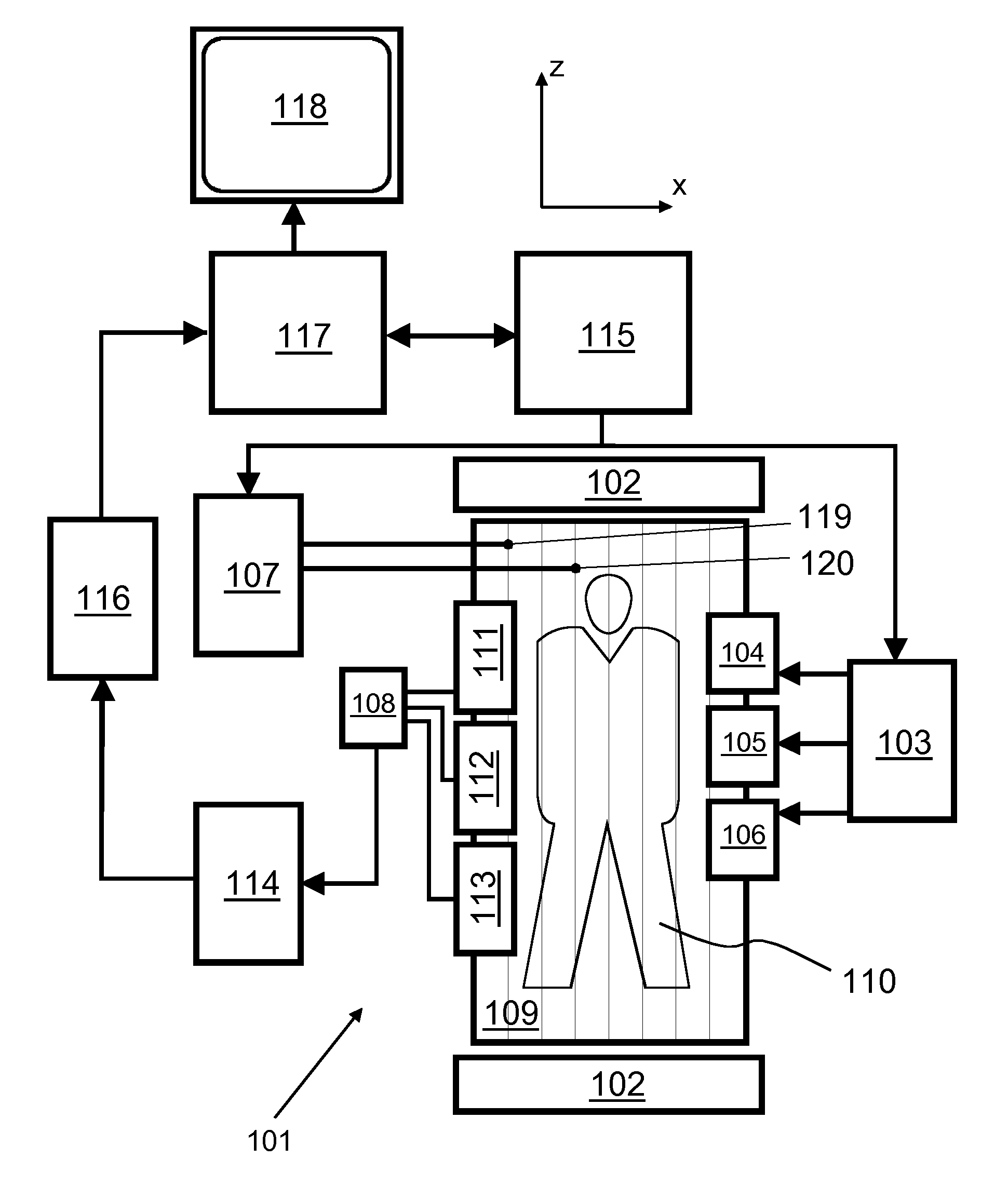
[0033]With reference to FIG. 1, a MR device 101 is shown. The device comprises superconducting or resistive main magnet coils 102 such that a substantially uniform, temporally constant main magnetic field is created along a z-axis through an examination volume.

[0034]A magnetic resonance generation and manipulation system applies a series of RF pulses and switched magnetic field gradients to invert or excite nuclear magnetic spins, induce magnetic resonance, refocus magnetic resonance, manipulate magnetic resonance, spatially and otherwise encode the magnetic resonance, saturate spins, and the like to perform MR imaging.

[0035]Most specifically, a gradient pulse amplifier 103 applies current pulses to selected ones of whole-body gradient coils 104, 105 and 106 along x, y and z-axes of the examination volume. A digital multi-channel RF frequency transmitter 107 transmits RF pulses or pulse packets via two RF drive ports 119, 120 to a whole-body volume RF coil 109 to transmit RF pulses ...


PUM


Abstract

The invention relates to a multi-channel (e.g. quadrature) MRI transmit system in which RF power amplifiers having different power capabilities are used in different transmit channels. This results in reduced system costs, due to the avoidance of an unused excess of RF power capability when the power demand for obtaining a homogeneous B1-field (RF shimming) is asymmetric and the asymmetry is qualitatively the same for different imaging applications. The multi-channel transmit unit may also comprise a commutator which enables to selectively connect each RF power amplifier to each drive port of transmit coil arrangement (e.g. a birdcage coil).

Description

FIELD OF THE INVENTION[0001]The invention relates to the field of magnetic resonance (MR) imaging. It concerns a method of MR imaging of at least a portion of a body of a patient placed in an examination volume of a MR device. The invention also relates to a MR device and to multi-channel transmit unit for a MR device.BACKGROUND OF THE INVENTION[0002]Image-forming MR methods which utilize the interaction between magnetic fields and nuclear spins in order to form two-dimensional or three-dimensional images are widely used nowadays, notably in the field of medical diagnostics, because for the imaging of soft tissue they are superior to other imaging methods in many respects, do not require ionizing radiation and are usually not invasive.[0003]According to the MR method in general, the body of the patient to be examined is arranged in a strong, uniform magnetic field whose direction at the same time defines an axis (normally the z-axis) of the co-ordinate system on which the measuremen...

Claims


Application Information

Patent Timeline
Patent Type & Authority Applications(United States)
IPC IPC(8): G01R33/34
CPCG01R33/34G01R33/3678G01R33/5612G01R33/5659
Inventor HARVEY, PAUL ROYSTONMENS, WILHELMUS REINERIUS MARIA
Owner KONINKLJIJKE PHILIPS NV
Why Eureka
Try Eureka