Isolation monitor

a technology of isolation monitor and isolation monitor, which is applied in the direction of electric devices, battery/fuel cell control arrangement, instruments, etc., can solve the problems of inability to detect the midpoint fault, prohibitively expensive isolation monitor based on this approach, and inability to meet safety standards

Active Publication Date: 2013-11-14
CURTIS INSTRUMENTS INC
View PDF16 Cites 83 Cited by
  • Summary
  • Abstract
  • Description
  • Claims
  • Application Information

AI Technical Summary

Benefits of technology

[0008]An isolation monitor imposes a switchable bias to a chassis through a set of high impedance resistors. In one implementation, switches are used to impose a changing voltage to the chassis through an upper and lower set of high impedance resistors. As a result, when there is no fault the measured isolation voltage swings up to known values. However, when there is a fault the chassis voltage does not swing to the known values. In addition to measuring isolation resistance the isolation monitor may also be configured to determine an approximate location of a fault, such as identifying a midpoint fault in a battery pack or induction motor.

Problems solved by technology

In the case of an electrically powered vehicle, examples of frame faults include the development of leakage paths from the battery pack, degradation of wires in an electric motor, or other faults in the high voltage electrical system.
There are several known techniques to determine isolation resistance in an electric vehicle, but each of these has significant drawbacks.
One way to determine isolation resistance is to measure the current into and out of the power source (e.g., at the battery leads), but an isolation monitor based on this approach that would be precise enough to meet safety standards would be prohibitively expensive for many applications.
However, the inventors of the present application have recognized that this approach does not detect certain types of faults.
For example, a fault at the precise midpoint of a battery pack has a symmetric effect on voltages such that this type of midpoint fault is undetectable using a simple voltage divider.
Thus, while there are techniques in the prior art to measure isolation resistance, these techniques are generally prohibitively expensive for many applications and generally also have problems in detecting certain types of faults, such as mid-point faults.

Method used


Image

  • Isolation monitor
  • Isolation monitor
  • Isolation monitor

Examples


Embodiment Construction

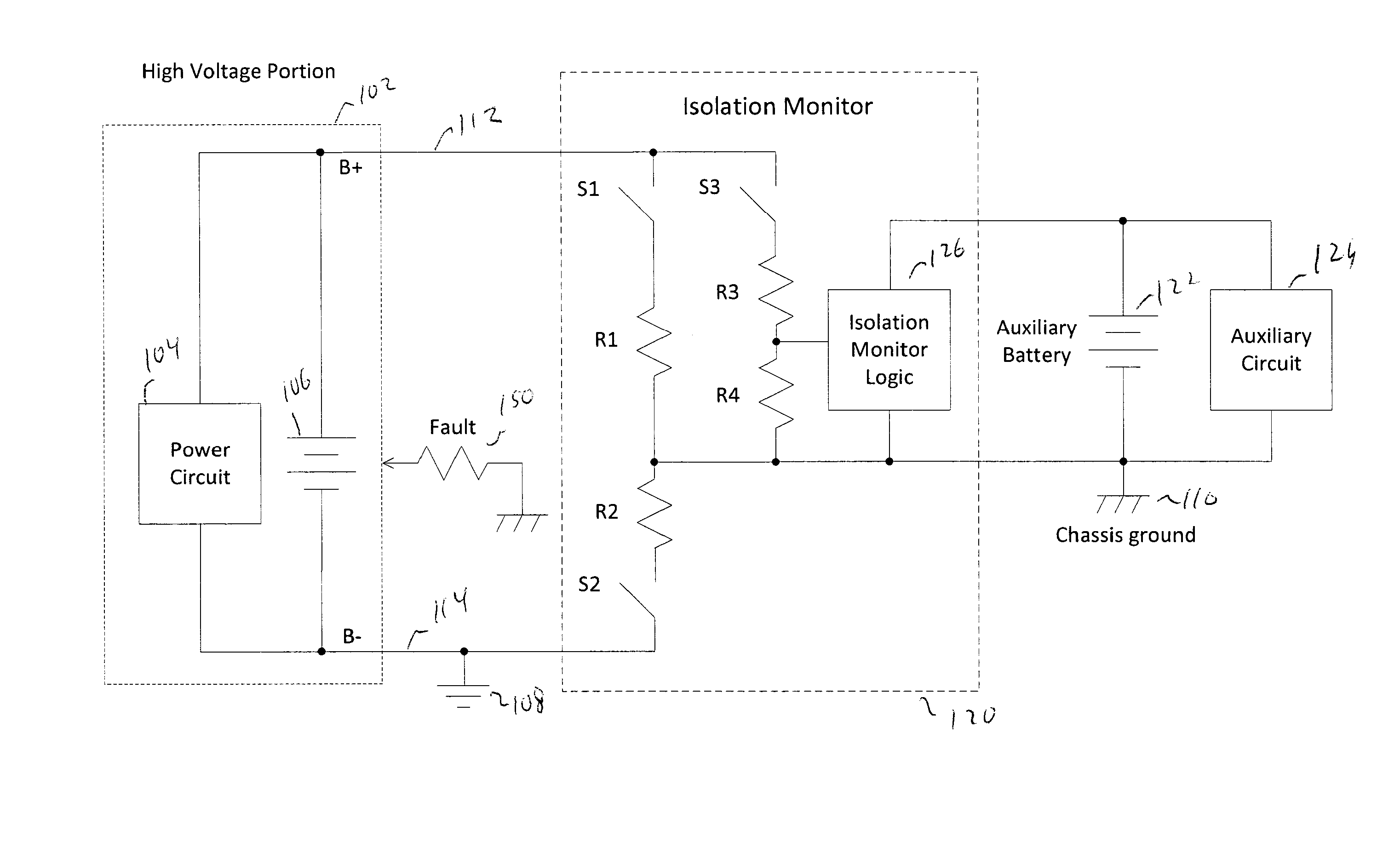
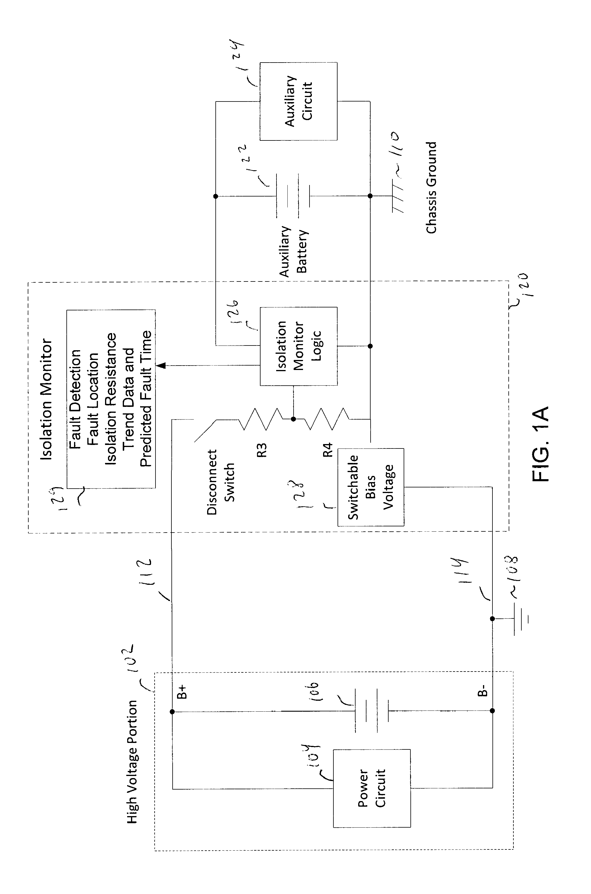
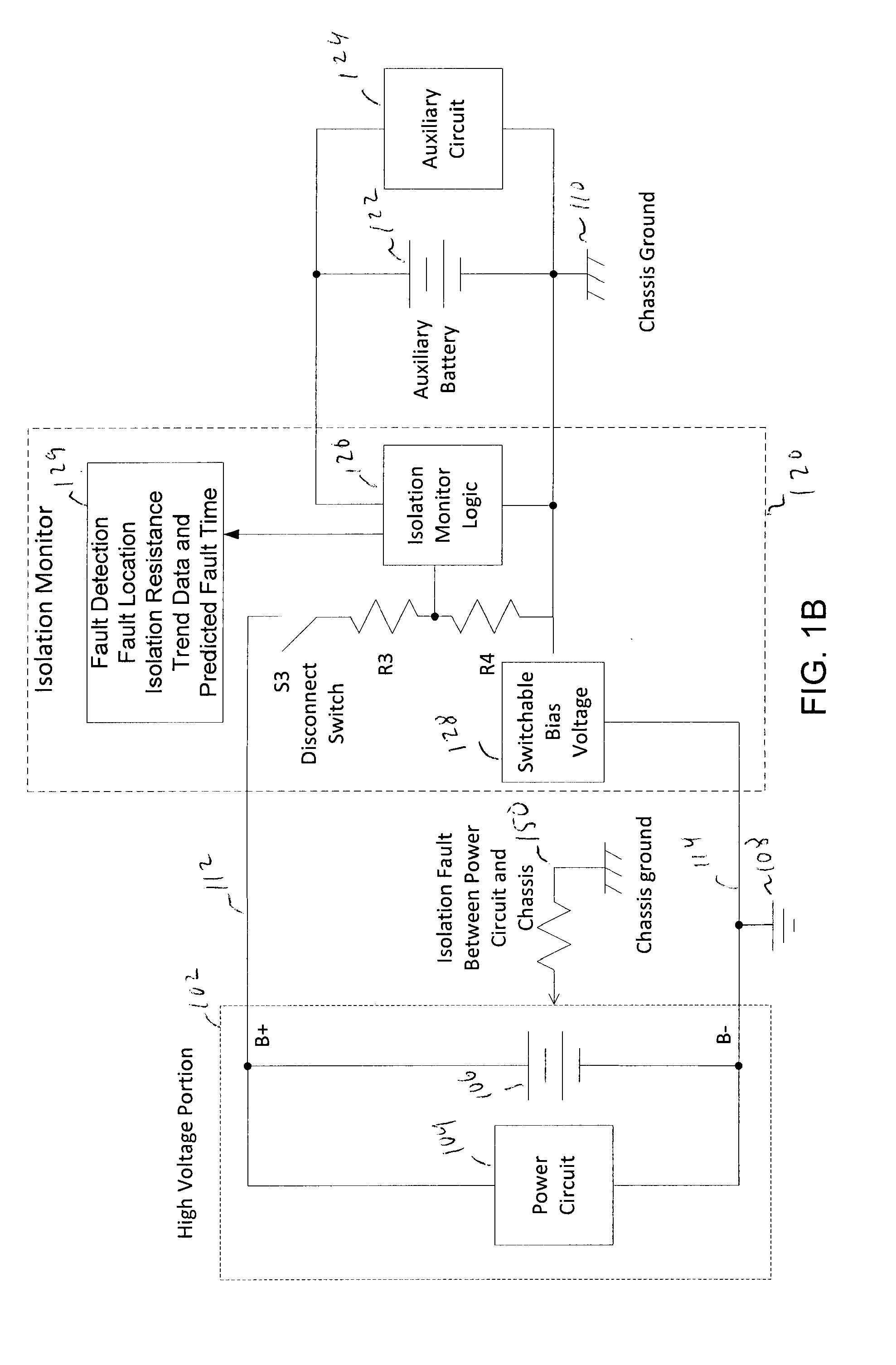
[0019]FIG. 1A is a high-level block diagram illustrating aspects of the present invention in an embodiment of the present invention. An electrical device has a high voltage circuit portion 102 with positive and negative battery power terminals B+ and B−, respectively. The high voltage circuit 102 drives a power circuit 104. In the case of an electric vehicle, the power circuit 104 may include a motor controller (not shown) to drive one or more electric motors. The total voltage of a battery 106 is “high” in the sense that it may pose an electrical shock risk to a human user in the event of an electrical fault. As an illustrative example, the battery 106 may be based on a battery pack having a set of batteries arranged in series such that the total battery voltage may be greater than 100 V.

[0020]The high voltage circuit portion 102 has its own ground potential 108. The high voltage circuit portion 102 is also designed to have a high degree of electrical isolation from a chassis groun...


PUM


Abstract

An isolation monitor is disclosed in which a switchable bias voltage is imposed on a chassis ground. An isolation voltage is measured when a bias voltage is applied. When there are no electrical faults, the isolation voltage swings up and down to known values. When a fault occurs, the isolation voltage will not to swing to the known values, and thus the isolation resistance can be measured and alarm generated if the isolation resistance falls below a threshold value.

Description

FIELD OF THE INVENTION[0001]The present invention is generally directed to electrical isolation monitoring. In particular, the present invention is directed to monitoring electrical isolation between a high voltage electrical system and a chassis frame. An exemplary application is for monitoring electrical isolation in an electric vehicle.BACKGROUND OF THE INVENTION[0002]An electric vehicle may include a vehicle chassis frame, a battery pack, and an electric motor. In some electric vehicles the total battery voltage for driving the vehicle is fairly high, e.g., 100-200 V or more. The high voltage circuits need to be isolated from the vehicle chassis frame for a variety of safety reasons, including protecting human health of users and technicians.[0003]There are various international safety standards for electric vehicles. Among these international safety standards are European safety standards for electrified vehicles that require that the high voltage circuits are isolated from the...

Claims


Application Information

Patent Timeline
Patent Type & Authority Applications(United States)
IPC IPC(8): G01R31/08
CPCB60L3/0007B60L3/0046B60L3/0061B60L3/0069B60L3/04B60L2240/547B60L2240/80B60L2250/10B60L2260/50B60L50/51B60L58/20B60L58/21G01R27/18G01R31/006G01R31/52Y02T10/70G01R31/08G01R31/085G01R31/088
Inventor LINDSAY, RYANWHITE, ROGERBOWMAN, SCOTTCOCHOY, JOHN
Owner CURTIS INSTRUMENTS INC
Why Eureka
Try Eureka