Patient monitoring and surveillance system, methods, and devices

Inactive Publication Date: 2013-11-14
LIFEFLOW TECH
View PDF8 Cites 88 Cited by
  • Summary
  • Abstract
  • Description
  • Claims
  • Application Information

AI Technical Summary

Benefits of technology

[0006]In some embodiments, the tag in the form of a card, fob, key, jewelry, clothing item, shoes or wearable patch to be in close proximity of the patient. In certain embodiments the tag is a wearable patch. In certain embodiments, the tag contains unique patient information. I

Problems solved by technology

As a result, urgent medical evaluation of non-critically ill patients only occurs a

Method used


Image

  • Patient monitoring and surveillance system, methods, and devices
  • Patient monitoring and surveillance system, methods, and devices
  • Patient monitoring and surveillance system, methods, and devices

Examples


example 1

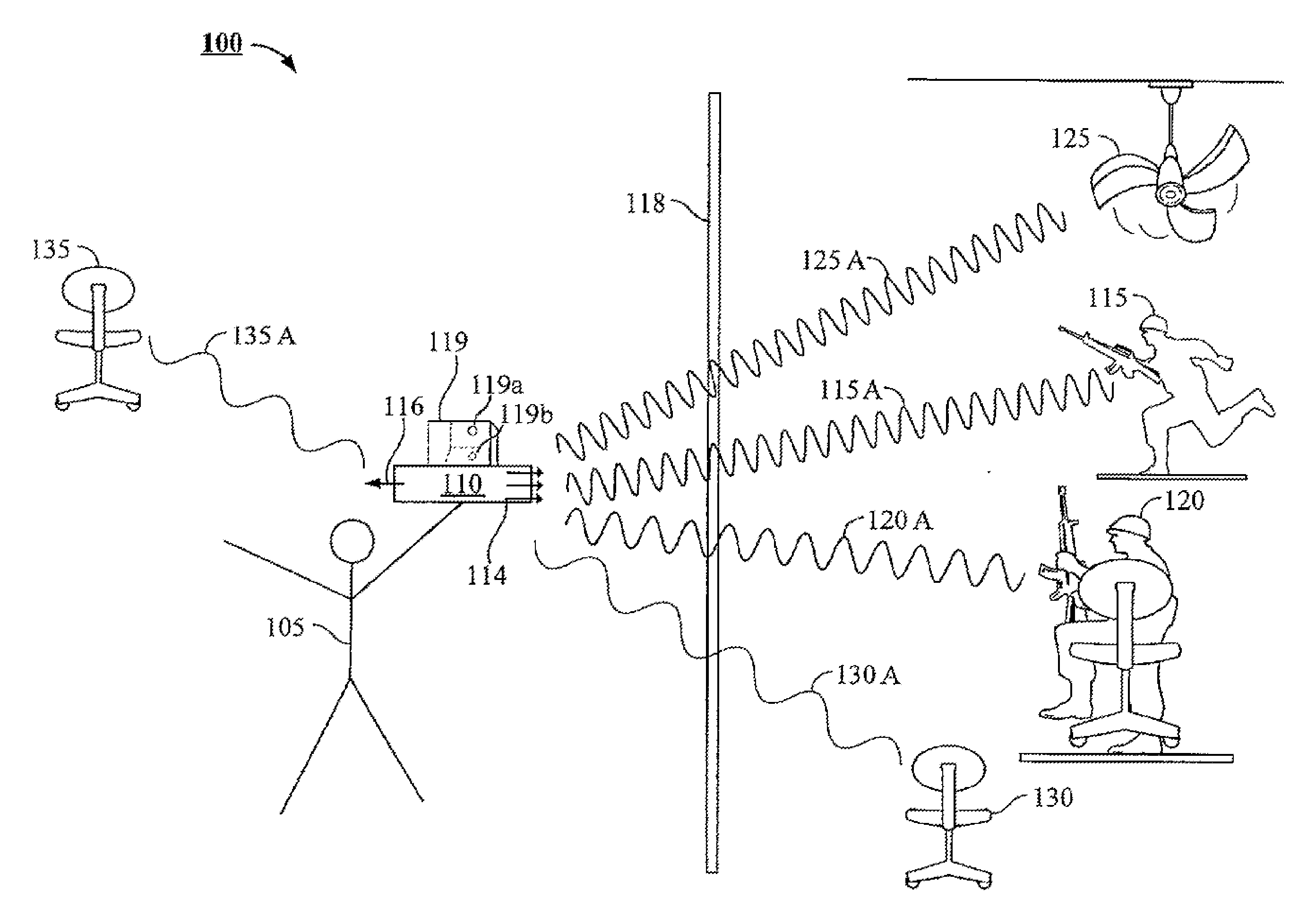
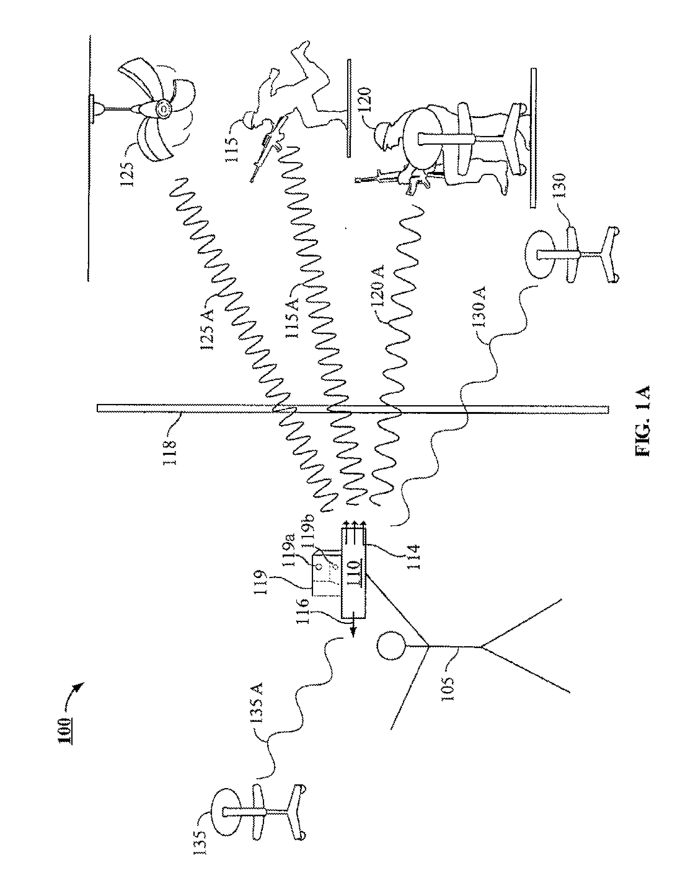
[0208]FIG. 4A shows a signal processing unit 2 in close proximity of a transmitter device 6 along with a separate receiver 12. A single antenna 8 is attached to the transmitter device and is depicted for simplicity, although multiple antennas may be used in the transmitter. An omni-directional signal 10 is transmitted and partially reflected by a patient 18 that is wearing a circular identification tag 20. The partially reflected signal 16 is received by receiving antenna 14. The signal processing unit 2 is configured to receive the frequency and phase information from both the transmitter and receiver device and is able to process the data to provide the vital signs, location, position and movement of patient 18 based on frequency and phase shifts between the transmitted signal and reflections of the transmitted signal. The circular identification tag 130 further provides the identity of patient 18 when receiving the transmitted signal and reflecting an identification signal. Here,...

example 2

[0209]FIG. 4B depicts a two patient room monitoring set up with two patient rooms 26 and 32 with adjoined bathrooms 28 and 34 respectively. In the middle of both patient rooms, is transmitter radar device 22 which transmits an omni-directional signal 24 into both patient rooms. In the patient rooms, patient 30 is lying on the ground of bathroom 28 while patient 36 is slightly on the bed in an abnormal position. Both patients are wearing circular patient information tags.

example 3

[0210]FIG. 10 is a display of two exemplary portable monitoring devices, 38 and 42. The portable monitoring device is configured to have a visual display 40 and 44. Display 40 and 44 displays information in four graphical panels that includes heart rate (HR), breathing rate (RR), position, and location of the two patients 30 and 36 of FIG. 4B as well as their identities, ‘A’ and ‘B’. In display 40, Patient A's heart rate, breathing rate, position and location are all outside of normal predetermined ranges which triggers an alarm on all four panels. In display 44, Patient B has a heart rate, breathing rate and location within normal predetermined ranges, however has an abnormal position of 45 degrees that is at risk of falling from the bed which triggers an alarm.


PUM


Abstract

Provided herein are methods, devices and systems for the remote monitoring and/or surveillance of a patient's location, position, movement, vital signs, biopotentials, or a combination thereof using transmission of stepped-frequency radar signals, detecting reflections of the transmitted signals and processing the frequency and phase shifts.

Description

RELATED APPLICATIONS[0001]This application claims the benefit of U.S. Provisional Patent Application No. 61 / 346,809, filed May 20, 2010, the contents of which are herein incorporated by reference in their entirety.BACKGROUND OF THE INVENTION[0002]Minimizing patient complications and decreasing length of hospital stay is of paramount importance to today's healthcare system where errors often cost lives and always cost money. Currently, standard non-critical patient monitoring protocols entail at best a nurse checking vital signs every 6 hours and more often only daily in sub-acute care facilities like rehabilitation wards and nursing homes. Generally, only the critically ill patients and those with active cardiac issues are able to be monitored continuously due to capital expenditure on equipment and staff limitations. As a result, urgent medical evaluation of non-critically ill patients only occurs after a patient has fallen or is critically ill for an indeterminate period of time.[...

Claims


Application Information

Patent Timeline
IPC IPC(8): A61B5/00
CPCA61B5/0002A61B5/01A61B5/02438A61B5/1113G01S7/40G01S13/36G01S13/42G01S13/4454A61B5/0507A61B2503/20A61B90/98A61B5/318A61B5/389A61B5/369
Inventor BROWN, DAVIDNORDIN, DAVIDTERAN, MANUEL
Owner LIFEFLOW TECH
Why Eureka
Try Eureka