Device and Method for Measuring Form Attributes, Position Attributes and Dimension Attributes of Machine Elements

a technology of position attributes and machine elements, applied in the direction of mechanical measuring arrangements, instruments, television systems, etc., can solve the problems of inability to measure shadow images, inability to adjust the position attribute, and large changeover times of the tacticile measurement method, etc., to achieve high precision, reduce construction expenditure, and high measuring accuracy

Inactive Publication Date: 2013-11-14
JENOPTIK IND METROLOGY GERMANY
View PDF0 Cites 27 Cited by
  • Summary
  • Abstract
  • Description
  • Claims
  • Application Information

AI Technical Summary

Benefits of technology

[0006]It is the object of the invention to find a possibility for measuring form attributes, position attributes or dimension attributes of a rotatable machine element which also allows surfaces having a substantial inclination relative to the rotational axis up to orthogonal orientation relative to the rotational axis as well as hidden regions such as undercuts, slopes, and irregularities, etc. to be measured with high measuring accuracy and with a lower expenditure on construction and simultaneously with high precision.

Problems solved by technology

However, tactile measuring methods generally require extensive changeover times when changing measuring tasks.
A disadvantage of optical measuring devices is that concave surface portions and undercuts, for example, which are not visible in the shadow image cannot be measured.

Method used


Image

  • Device and Method for Measuring Form Attributes, Position Attributes and Dimension Attributes of Machine Elements
  • Device and Method for Measuring Form Attributes, Position Attributes and Dimension Attributes of Machine Elements
  • Device and Method for Measuring Form Attributes, Position Attributes and Dimension Attributes of Machine Elements

Examples


Embodiment Construction

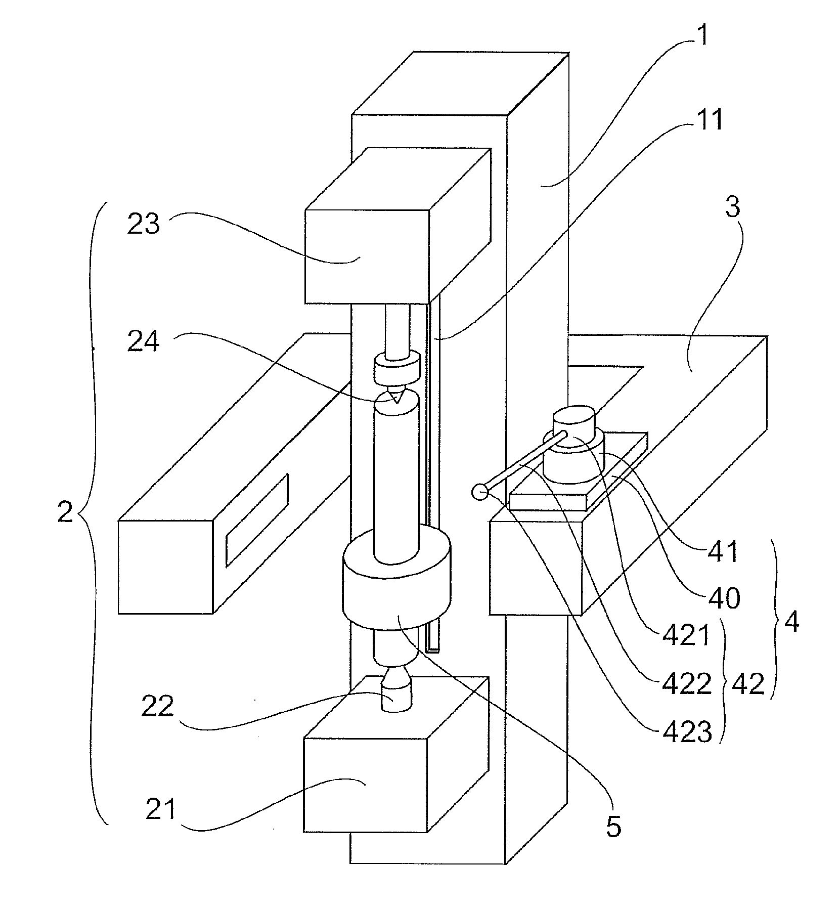
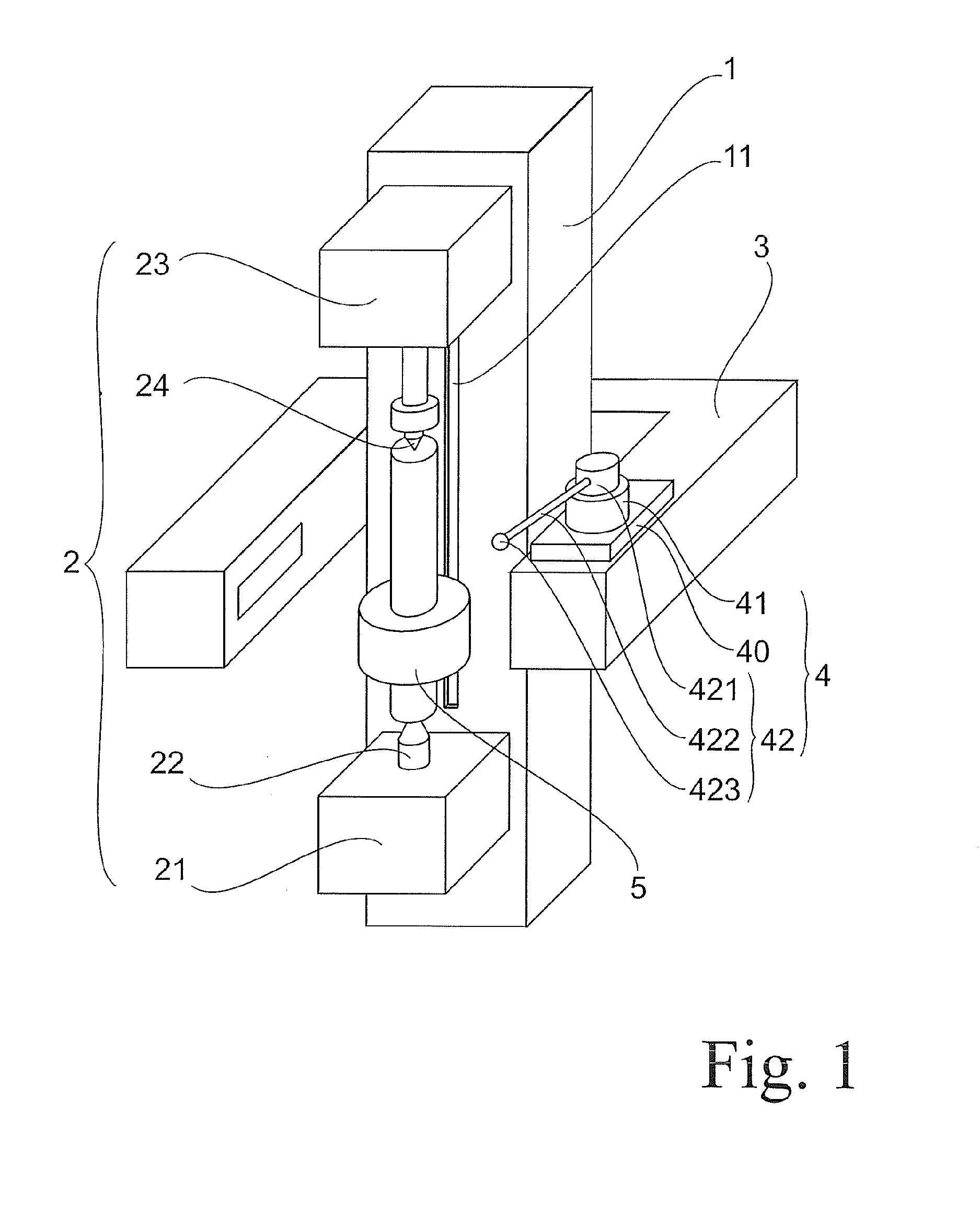
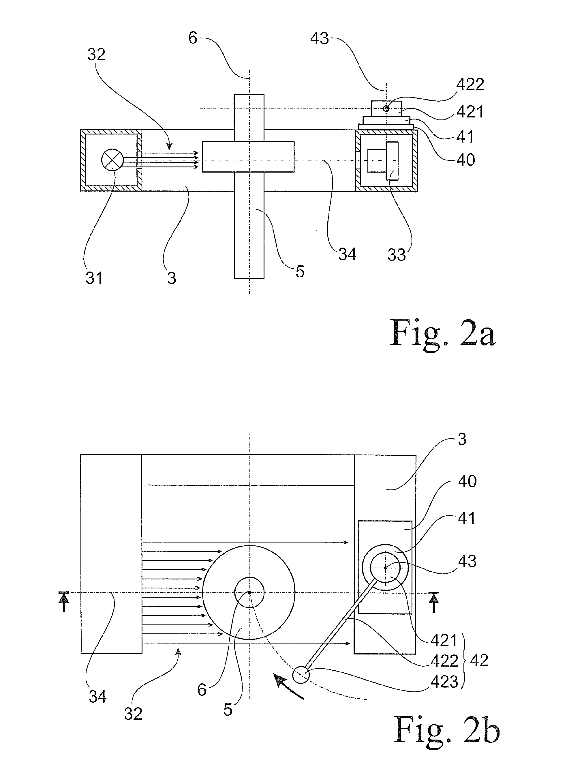
[0038]The basic construction of the device is shown in FIG. 1. The device substantially comprises a mechanically stable machine bed 1 at which a workpiece holder 2 and an optical measuring unit 3 are movably arranged. The workpiece holder 2 has a driven center 22 and a live or revolving center 24 forming a rotational axis 6 and between which a machine element 5 can be received on the rotational axis 6. The optical measuring unit 3 is arranged so as to face the machine element 5 on both sides of the rotational axis 6. For optical measurement of the machine element 5, the optical measuring unit 3 has an illumination module 31 on one side of the rotational axis 6 and a camera module 33 on the opposite side of the rotational axis 6. A swiveling device 41 is fixedly arranged on one side of the optical measuring unit 3. The swiveling device 41 has a mechanical measuring unit 4 which is swivelable orthogonal to the rotational axis 6.

[0039]The workpiece holder 2 comprises a headstock 21 whi...


PUM


Abstract

A device and a method for measuring form attributes, position attributes and dimension attributes of rotatable machine elements are described. It is the object of the invention to find a possibility for measuring form attributes, position attributes or dimension attributes of a rotatable machine element which also allows axially probeable surfaces having hidden regions to be measured with high accuracy with a lower expenditure on construction. According to the invention, this object is met in that a mechanical measuring unit having a tactile measuring probe for measuring the machine element in axial direction is provided in addition to an optical measuring unit with illumination module and camera module which captures a shadow image of the machine element. The mechanical measuring unit is fixed to the optical measuring unit and has a swiveling device for swiveling the tactile measuring probe orthogonal to the rotational axis of the machine element.

Description

RELATED APPLICATIONS[0001]This application claims priority to German Patent Application No. DE 10 2012 104 008.7, filed May 8, 2012, which is incorporated herein by reference in its entirety.FIELD OF THE INVENTION[0002]The invention is directed to a device and a method for measuring form attributes, position attributes and dimension attributes of rotatable machine elements such as, for example, engine shafts and transmission shafts, thrust rods, valves, pistons, screws, turbine parts, etc.BACKGROUND OF THE INVENTION[0003]Tactile measuring methods in which surfaces are probed by mechanical probing elements and can be measured very precisely have become established for precise measurement of shafts. However, tactile measuring methods generally require extensive changeover times when changing measuring tasks.[0004]In such cases, optical measuring methods are available. These optical measuring methods generate a shadow image of the shaft by which the outer contour can be measured. Owing...

Claims


Application Information

Patent Timeline
Patent Type & Authority Applications(United States)
IPC IPC(8): G01B21/02G01B21/16G01B21/20
CPCG01B21/02G01B21/20G01B21/16G01B11/08G01B5/285G01B5/012G01B11/2433G01B11/24
Inventor NEUMANN, ERNSTSCHUBERT, MICHAEL
Owner JENOPTIK IND METROLOGY GERMANY
Why Eureka
Try Eureka