

Method of measuring a capacitance
a capacitance and sensor technology, applied in the direction of electric digital data processing, chemical methods analysis, instruments, etc., can solve the problems of working electrodes being finally worn, working electrodes having to be replaced for new ones, and known methods using biosensors for measuring changes in dielectric properties, etc., to achieve the effect of eliminating one or more deficiencies and disadvantages
- Summary
- Abstract
- Description
- Claims
- Application Information
AI Technical Summary
Benefits of technology
Problems solved by technology
Method used
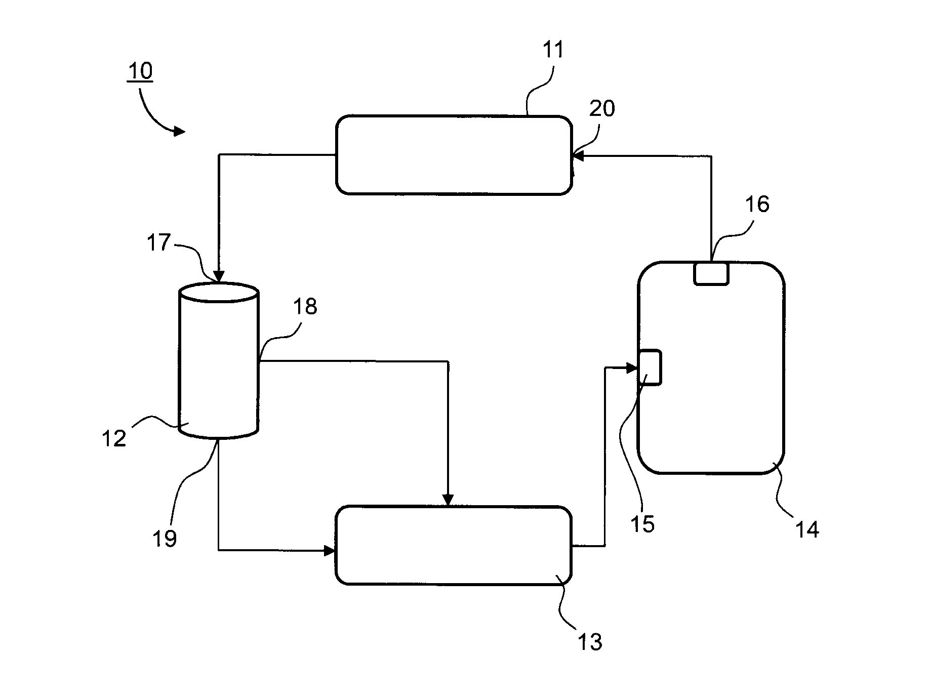
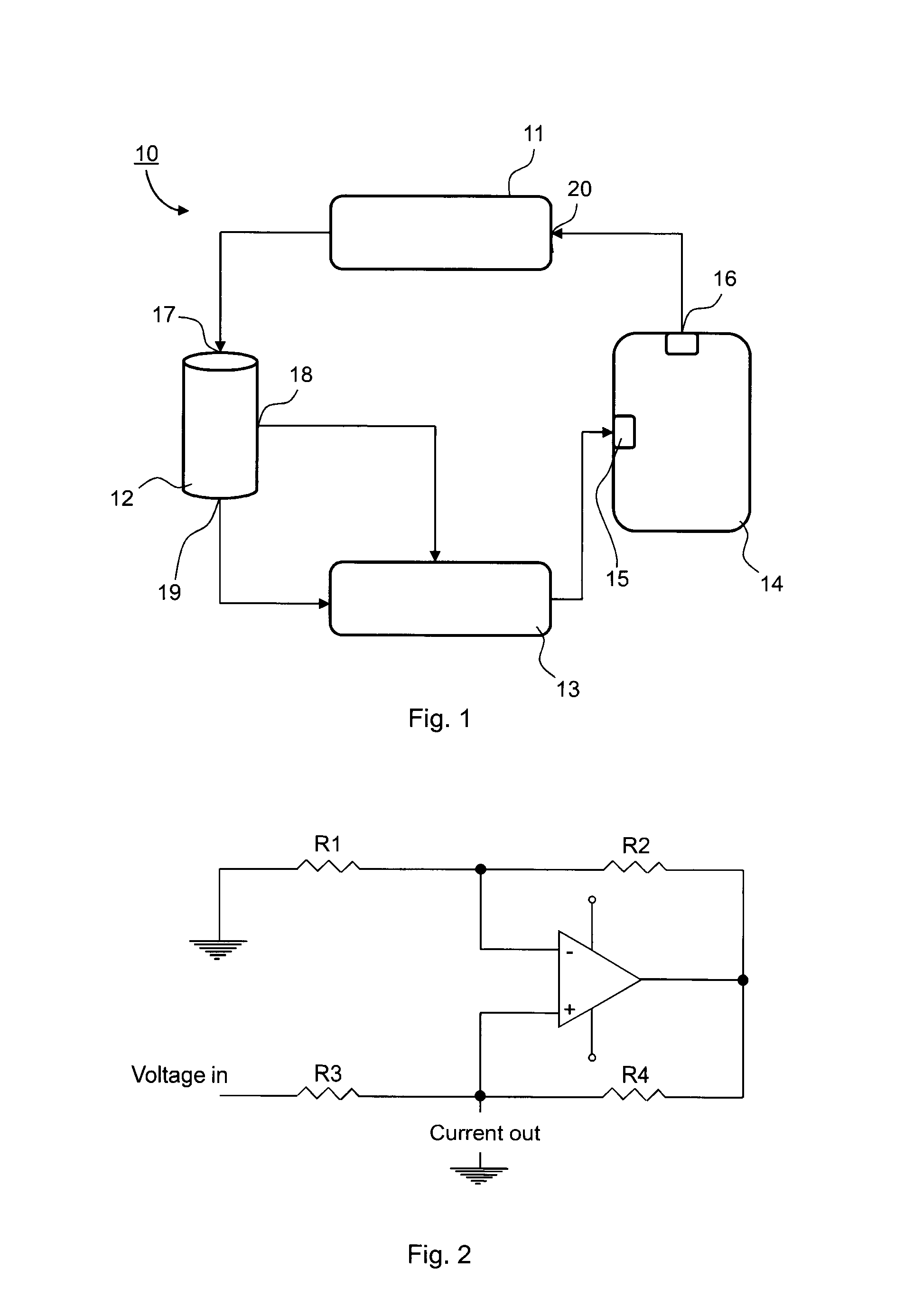
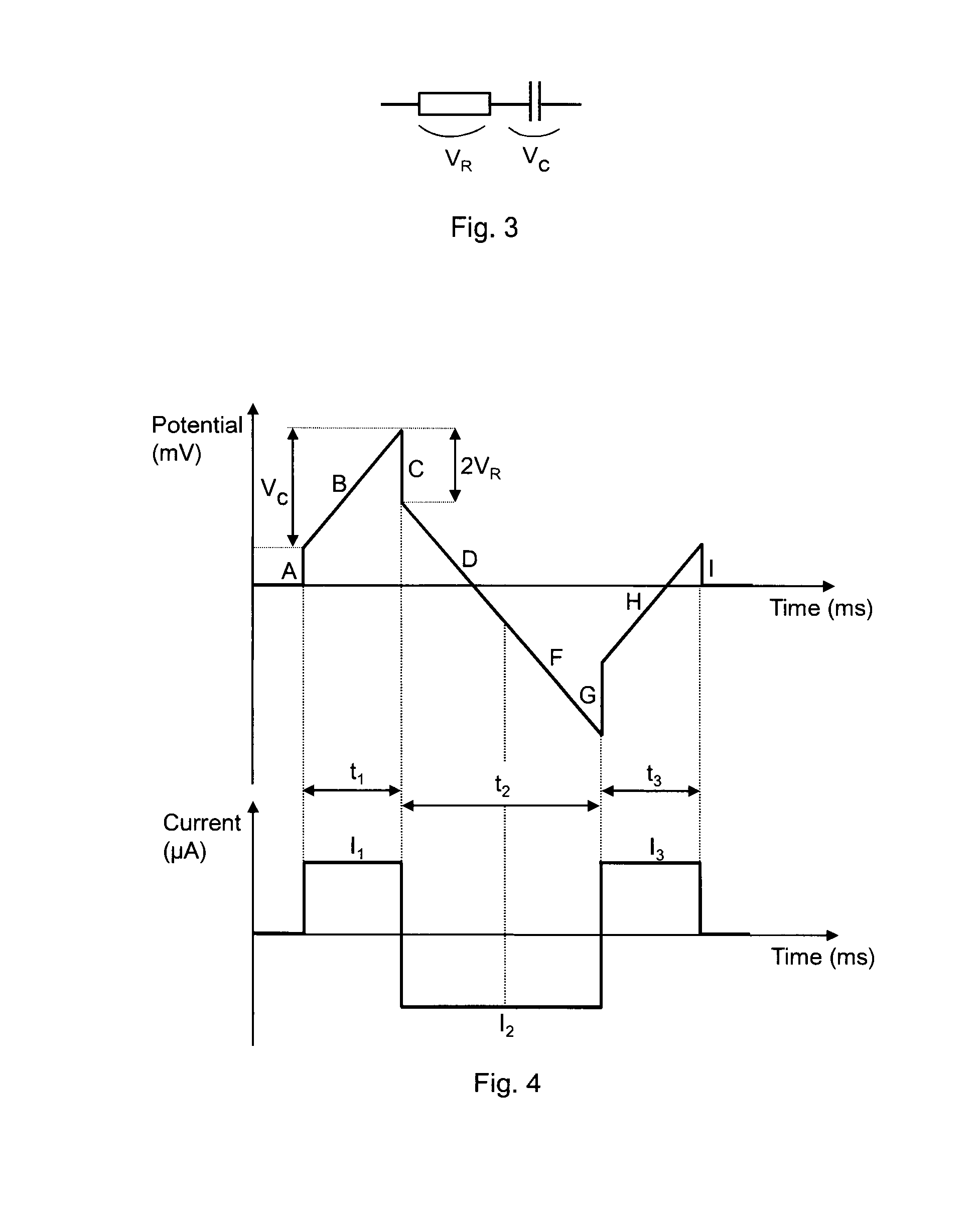
Image

Examples
example
[0101]1. Prior Art System
[0102]Cholera Concentration 1
C (nF)Delta (nF)standard deviation236.35235.960.39236.11−0.15236.55−0.44235.750.8235.85−0.10.306447
[0103]2. Prior Art System
[0104]Cholera Concentration 2
C (nF)Delta (nF)standard deviation255.37256.411.04255.67−0.74255.740.07256.761.02255.49−1.270.552618
[0105]3. Inventive System
[0106]Cholera Concentration 3
C (nF)Delta (nF)standard deviation147.078147.0670.011147.0540.013147.0520.002147.0310.021147.06−0.0290.015875
[0107]Several advantages for measuring the capacitance, by using electrochemical principles, are achieved by the inventive method compared to existing measuring methods within the biochemical field.
[0108]The invention contributes to achieve reliable and accurate values of the capacitance, which can be used for different applications. Examples of such applications are determination of concentrations of specific agents present in any type of fluid, specifically by using a suitable ligand for determinatio...
PUM
| Property | Measurement | Unit |
|---|---|---|
| time | aaaaa | aaaaa |
| time | aaaaa | aaaaa |
| capacitance | aaaaa | aaaaa |
Abstract
Description
Claims
Application Information