Hybrid vertical drainpipe heat exchanger

a heat exchanger and drainpipe technology, applied in the direction of indirect heat exchangers, stationary tubular conduit assemblies, lighting and heating apparatus, etc., can solve the problems of limited length of vertical installations and limit the wetted surface area

Inactive Publication Date: 2013-11-21
MACKELVIE WINSTON
View PDF7 Cites 19 Cited by
  • Summary
  • Abstract
  • Description
  • Claims
  • Application Information

AI Technical Summary

Benefits of technology

[0011]The diametric dimensions of the components ensures that upon final assembly of the components, the first describe...

Problems solved by technology

Typically, vertical installations are limited in length by ceiling-to-...

Method used


Image

  • Hybrid vertical drainpipe heat exchanger
  • Hybrid vertical drainpipe heat exchanger

Examples


Embodiment Construction

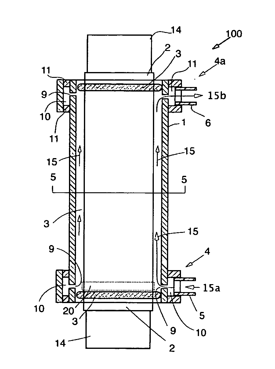
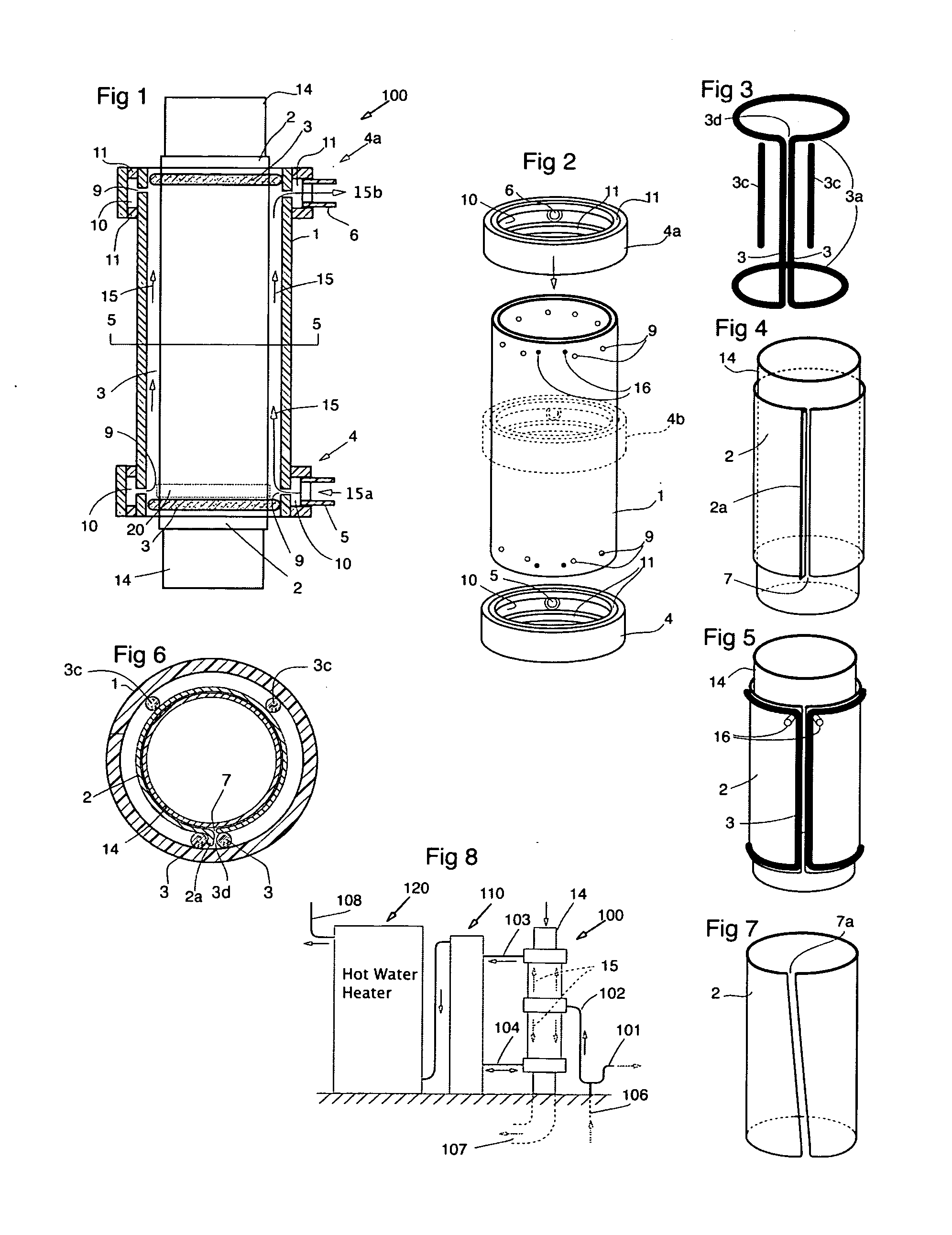
[0021]Referring to the drawings, FIG. 1 shows a cross section of the drainpipe heat exchanger 100. The central drainpipe 14 may be a common copper DWV (domestic waste vent) tube or pipe of any suitable diameter from, say, 2 to 6 inches. It may also be rolled and seamed from any suitable sheet material. In FIGS. 1 and 2 outer tube 1 may be of any suitable still material such as a PVC or ABS plastic tube or pipe capable of withstanding pressure from within and sized in accordance with the diameter of drainpipe 14. Outer tube 1 has fluid openings adjacent each end preferably in the form of a ring of holes 9 through the wall for fluid distribution.

[0022]Inlet manifold 4 (lower) and outlet manifold 4a (upper) have inlet 5 and outlet 6 fittings (inlet flow 15a, outlet flow 15b) and an internal circumferential flow channels 10 that communicate with their respective distribution holes 9 in outer tube 1. As shown in FIG. 2 the manifolds arrows indicate they are to be slid on over each end of...


PUM

PropertyMeasurementUnit
Electrical conductoraaaaaaaaaa
Heataaaaaaaaaa
Distributionaaaaaaaaaa

Abstract

A low-cost hybrid heat exchanger uses sheet copper and rigid plastic tubing. Copper is used only where actual heat transfer takes place, adjacent the drainpipe wall. All other components are plastic to lower cost. It pre-heats fresh cold water using waste heat from the drain such as from a shower drain. The heat exchanger comprises an inner copper conduit or drainpipe, a rolled sheet copper cylinder, an outer plastic tube and manifolds, and O-ring. On assembly, inserting the drainpipe results in the O-ring being compressed between the copper cylinder and the plastic tube. The result is a sealed water chamber wherein heat transfer takes place. The ends of the plastic tube have radially spaced water distribution holes into the chamber and inlet and outlet manifolds, each with water connections to the building's cold water supply. A method of recovering heat from non-shower hot water uses using a separate reservoir is also disclosed.

Description

FIELD OF THE INVENTION[0001]The present invention is in the field of heat exchangers and more particularly drainpipe heat exchangers for drainwater heat recovery from vertical drainpipes.BACKGROUND OF THE INVENTION[0002]Drainwater is a low-level heat source. As such it requires a low cost heat exchanger in order that home and building owners can recover its cost in a reasonable time.SUMMARY OF THE INVENTION[0003]While it may be used in a variety of heat transfer applications, instant heat exchanger's use in heat recovery from a building's wastewater drainpipe will be described in detail herein. The instant heat exchanger is suitable for both vertical and horizontal installations. When installed vertically it operates as a falling film heat exchanger where the drainwater flows circumferentially on the inner wall which maximizes the wetter surface area needed for heat transfer. Typically, vertical installations are limited in length by ceiling-to-floor dimensions in buildings which, i...

Claims


Application Information

Patent Timeline
IPC IPC(8): F28F1/00
CPCF28F1/00F28F9/02F28F21/062F28F21/085F28D7/106F28D15/00F28D21/0012F28F1/003E03C2001/005F28F2230/00Y02B30/56
Inventor MACKELVIE, WINSTON
Owner MACKELVIE WINSTON
Why Eureka
Try Eureka