Wire harness, wire harness manufacturing method and wire harness manufacturing apparatus

a manufacturing method and wire harness technology, applied in the direction of insulating conductors/cables, cables, insulated conductors, etc., can solve the problems of reducing working efficiency, affecting the appearance of tape-wrapped parts, and the inability to set electric wires in such apparatuses, so as to reduce the number of process steps, reduce the number of wire harness parts, and reduce the manufacturing cost

Inactive Publication Date: 2013-11-21
AUTONETWORKS TECH LTD +2
View PDF5 Cites 7 Cited by
  • Summary
  • Abstract
  • Description
  • Claims
  • Application Information

AI Technical Summary

Benefits of technology

[0039]In the wire harness manufacturing method according to the present invention, the order of the step of attaching a connector or the like to the end of the electric wire and the step of molding the covering member in the predetermined part of the electric wire is not limited. Accordingly, in the wire harness manufacturing method according to the present invention, it is possible to attach predetermined connectors and the like to the ends of the respective electric wires then bundle the electric wires, and mold the covering member. Accordingly, the step of attaching the connectors and the like to the ends of the electric wires is performed in a state where each electric wire individually exists. Accordingly, at the step of attaching the connectors and the like using a device to automatically attach the connectors and the like, there is no difficulty in setting of the connectors and the like due to interference with other electric wires or covering member. It is therefore possible to perform the step of attaching the connectors and the like to the respective electric wires using the device to automatically attach the connector and the like, and reduce the manufacturing cost.
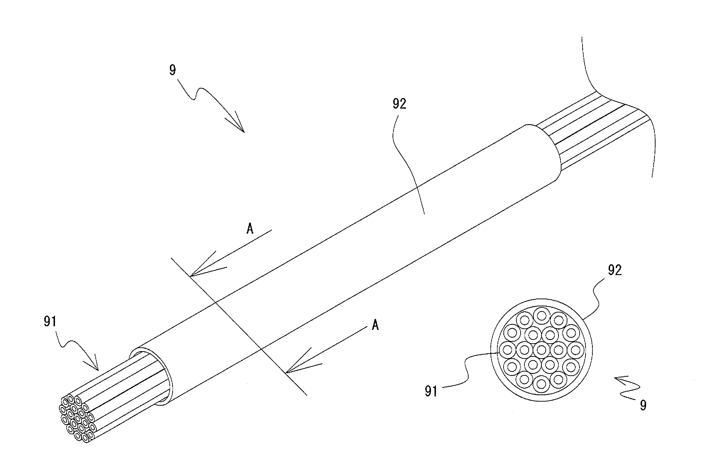
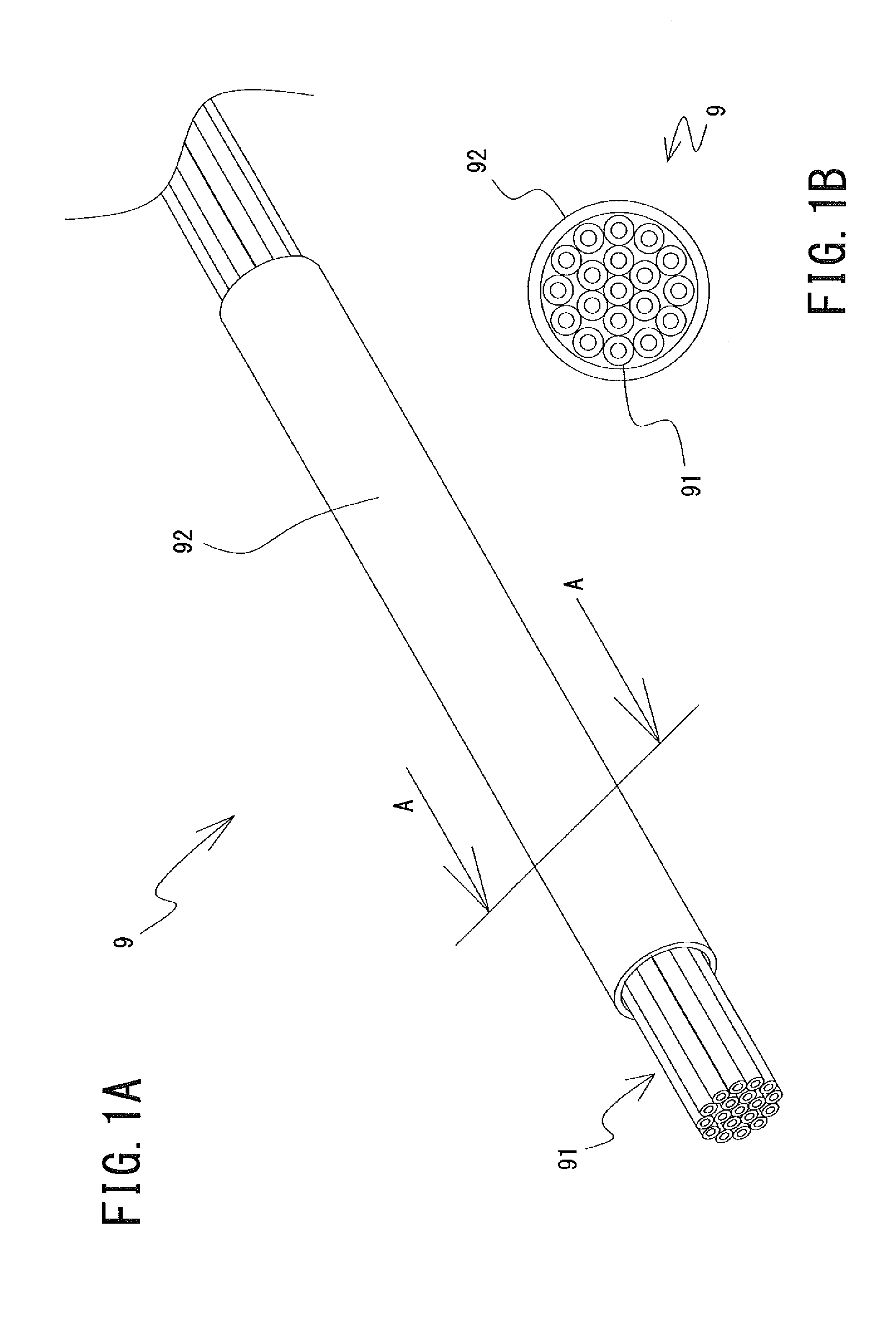
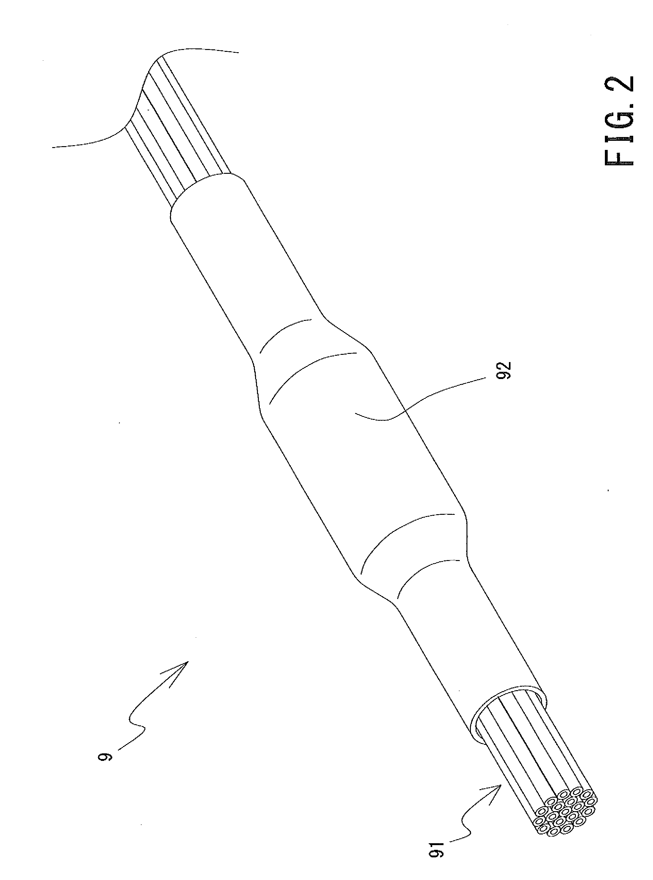
[0040]Further, in the wire harness manufacturing method according to embodiments of the present invention, it is possible to mold a covering member 92 in which the thickness changes along an axial direction (i.e., a covering member in which the strength changes) simply and integrally. More particularly, during molding of the covering member, the thickness of the covering member can be adjusted only by controlling the speed of relative movement of the nozzle with respect to a predetermined part of the electric wire and / or the amount of thermoplastic material discharged from the discharge orifice of the nozzle per unit time. That is, it is possible to integrally mold the covering member in which the thickness changes along the axial direction. Accordingly, as it is not necessary to provide plural covering members, it is possible to reduce the number of process steps. Further, since it is possible to integrally mold the covering member in which the thickness changes along the axial direction with the thermoplastic material, it is possible to reduce the number of parts of the wire harness.
[0041]In the wire harness manufacturing method according to the embodiments of the present invention, it is possible to cut the molded covering member at its terminal end without causing plastic deformation of the covering member by pulling it out. Accordingly, the appearance of the covering member in the axial direction can be improved.
[0042]When an air blowing unit sends air to the molded covering member, the covering member is quickly cooled down. Accordingly, plastic deformation by thermal plasticity does not occur in the covering member. On the other hand, since the thermoplastic material existing in the nozzle does not receive air sent from the air blowing unit and is not cooled, plastic deformation by thermal plasticity easily occurs. As a result, a border between a part in which the plastic deformation by thermal plasticity does not occur and a part in which the plastic deformation by thermal plasticity easily occurs, is formed in thermoplastic material (including the formed covering member) in the position of the discharge orifice of the nozzle.
[0043]In this state, when the nozzle and the predetermined part of the electric wire are relatively moved, the thermoplastic material existing in the nozzle remains in the nozzle by a friction force or the like. On the other hand, in the part (molded covering member) of the thermoplastic material discharged from the discharge orifice of the nozzle, plastic deformation by thermo plasticity does not occur, therefore it is not plastic-deformed even when a pulling force in the axial direction is applied. Accordingly, at the thermoplastic material discharge orifice of the nozzle (i.e., on the border between the thermoplastic-deformable part and the undeformable part), it is possible to cut the molded covering member and the thermoplastic material before molding without causing plastic deformation by pulling out the respective parts.

Problems solved by technology

However, these structures may have the following problems.
This might reduce working efficiency.
In addition, the appearance of the tape-wrapped part is bad.
When an apparatus to automatically attach connectors and the like to the ends of electric wires may be used, however, when the electric wire group is accommodated in the tube, it is impossible to set the electric wires in such apparatus due to interference with the tube and / or the other electric wires in some cases.
In this case, since it is impossible to automatically attach the connectors and the like to the ends of the electric wires, it is necessary to manually attach the connectors or the like.
It is difficult to reduce the manufacturing cost of the wire harness.
Since the number of process steps is increased, it is difficult to reduce the manufacturing cost.
Further, the appearance of the tape-wrapped tube is bad.
Further, the tube used for the wire harness generally lacks a positioning mechanism with respect to the predetermined part of electric wire(s).
Accordingly, it is difficult to reduce the number of process steps.
Further, the appearance of the wrapped tape is bad.
Generally, since a molding die is expensive and is not very versatile, this structure using such molding die might increase the equipment cost.
For a reason similar to that in the above structure, the structure might increase the equipment cost.
Further, in this structure, it is difficult to change the thickness of the molded part.
However, since the structure is approximately the same as a structure to mold a member to cover a core wire of an electric wire, it is difficult to change the thickness of the member.

Method used


Image

  • Wire harness, wire harness manufacturing method and wire harness manufacturing apparatus
  • Wire harness, wire harness manufacturing method and wire harness manufacturing apparatus
  • Wire harness, wire harness manufacturing method and wire harness manufacturing apparatus

Examples


first embodiment

[0078]Next, a wire harness manufacturing apparatus 1 according to the present invention will be described.

[0079]FIG. 3 is a schematic diagram showing principal elements in the structure of the wire harness manufacturing apparatus 1 according to the first embodiment of the present invention. As shown in FIG. 3, the wire harness manufacturing apparatus 1 according to the first embodiment of the present invention has a material plasticizing unit 11, a nozzle 12, and an air blowing unit 13. The wire harness manufacturing apparatus 1 according to the first embodiment of the present invention molds the covering member 92 so as to cover the electric wire 91 by heat-plasticizing thermoplastic material as the material of the covering member by the material plasticizing unit 11 and feeding the material through a hose (member as a channel of the thermoplastic material) 14 or the like to the nozzle 12, and discharging the plasticized thermoplastic material from the nozzle 12. Further, the air b...

second embodiment

[0143]As a modification of the above-described wire harness manufacturing apparatus 2 the following example can be given.

[0144]As shown in FIG. 11, the thermoplastic material channels 2231 and 2241 have predetermined positions on the side of the hose engagement members 223b and 224b as start points, and extend from the start points in the planar direction of the flat plate members 223a and 224a by a predetermined length, and branch into two channels. Further, the channels extend in the planar direction of the flat plate members 223a and 224a by a predetermined length, and respectively branch into two branches, i.e., total four branches. Since the thermoplastic material channels 2231 and 2241 formed in this manner are formed so as to extend in the planar direction different from the direction in the first embodiment, the length from the start points to the end points of the respective channels are different.

[0145]Accordingly, assuming that the respective channels have the same cross...


PUM

PropertyMeasurementUnit
temperatureaaaaaaaaaa
lengthaaaaaaaaaa
temperatureaaaaaaaaaa

Abstract

A wire harness manufacturing method prevents inadvertent deformation of thermoplastic material and separation of thermoplastic material. A predetermined part of an electric wire 91 is accommodated in a through hole of a tubular body formed by connection between a first and second nest members (123, 124) of a nozzle (12), by integrally connecting first and second case body members (121, 122) of the nozzle (12), with the predetermined part of the electric wire 91 therebetween. An approximately tubular covering member (92) covering the predetermined part of the electric wire (91) is molded integrally with the thermoplastic material, by discharging thermoplastic material plasticized by a material plasticizing unit (11) from thermoplastic material discharge orifices (1213) and (1223) in the nozzle (12) to the outer periphery of the electric wire (91), while moving the electric wire (91) and the nozzle (12) relatively to each other.

Description

BACKGROUND OF THE INVENTION[0001]1. Field of the Invention[0002]The present invention relates to a wire harness, a wire harness manufacturing method and a wire harness manufacturing apparatus, and more particularly, to a wire harness in which a predetermined part of electric wire is provided with a member having a function of protecting the electric wire and / or a function of bundling plural electric wires, a method for manufacturing the wire harness, and an apparatus capable of manufacturing the wire harness (wire harness manufacturing apparatus).[0003]2. Description of the Related Art[0004]In a vehicle such as an automobile, a wire harness to mutually connect electric devices and electronic devices is arranged. The wire harness used for such application generally has predetermined types and predetermined lengths of plural electric wires. These plural electric wires are bound (or bundled) in a predetermined form. Further, predetermined types of connectors and the like are attached t...

Claims


Application Information

Patent Timeline
Patent Type & Authority Applications(United States)
IPC IPC(8): B05D7/20H01B7/00B29C48/06B29C48/32B29C48/90
CPCB05D7/20H01B7/0045H01B13/24B29C48/06B29C48/12B29C48/91B29C48/154B29C48/911B29C48/2566B29C48/32B29C48/908H01B13/01263H01B13/0013
Inventor SATO, OSAMU
Owner AUTONETWORKS TECH LTD
Why Eureka
Try Eureka